I. Introduction CAN bus is a communication protocol developed by German BOSCH in the early 1980s to solve the data exchange between many control and test instruments in automobiles. Due to its outstanding reliability, real-time and flexibility, the CAN bus has been widely recognized and used by the industry. It officially became an international standard and industry standard in 1993 and is known as the “most promising fieldbusâ€. one. The application of the bus technology represented by CAN in the automobile not only reduces the wiring harness of the vehicle body, but also improves the reliability of the automobile. In the design of modern foreign cars, CAN has become a must-have technology. Mercedes-Benz, BMW, Volkswagen, Volvo and Renault have used CAN as a means of networking controllers. There is a big gap in the application of CAN bus technology in automobiles in China. The research on the application of CAN bus technology in electric vehicles is still in its infancy.
Electric vehicles incorporate many electronic control systems, such as battery management systems, motor control systems, drive control systems, regenerative braking systems, and ABS systems. The large number of applications of electronic equipment will inevitably lead to the growth and complexity of the body wiring, the reduction of the operational reliability, the increase of power loss on the line, and the difficulty of fault maintenance. In particular, the introduction of electronic control units, in order to improve the utilization of signals, requires a large amount of data information to be shared among different electronic units. A large number of control signals in the integrated control system of the vehicle also need to be exchanged in real time. The traditional wiring harness is far from being able to Meet this need. The introduction of CAN bus technology into electric vehicles can overcome the above shortcomings and has broad application prospects. In this paper, the CAN bus technology is applied to the electric vehicle control system, and the universal expansion unit is used to solve the circuit design complexity of the electric vehicle electronic control system. The information of each electronic control unit is optimized to achieve sufficient information sharing to improve the electric vehicle control system. The purpose of performance.
Second, CAN bus characteristics CAN belongs to the field bus category, is a serial communication network that effectively supports distributed control or real-time control. CAN bus is widely used in the field of industrial control thanks to its own technical characteristics.
(1) Only through message filtering, point-to-point, point-to-multipoint and global broadcast can be transmitted and received in several ways, without special “schedulingâ€.
(2) The communication method is flexible. CAN works in a multi-master mode, and any node on the network can actively send information to other nodes on the network at any time, without sub-master and without node information such as site address.
(3) CAN adopts non-destructive bus arbitration technology. When multiple nodes send information to the bus at the same time, the node with lower priority will actively exit the transmission, and the node with the highest priority can continue to transmit data without affecting. The bus conflict arbitration time is greatly saved, especially in the case of heavy network load.
(4) Communication in short frame format, short transmission time, low probability of interference, and excellent error detection effect. The maximum number of bytes per frame is 8, which can meet the general requirements of control commands, working status and test data in the general industrial field. At the same time, 8B does not take up too long bus time, thus ensuring the real-time communication.
(5) Each frame of CAN has CRC check and other error detection measures to ensure the reliability of data communication.
Third, CAN bus application in electric vehicles CAN bus has the following advantages in electric vehicles.
(1) Reduce the number and volume of harnesses required for each functional module.
(2) Reduce the quality of the whole vehicle and reduce the cost of the vehicle. It has high data transmission and installation convenience, and expands the vehicle function.
(3) Some data such as vehicle speed, motor speed and SOC can be shared on the bus, so redundant sensors are removed, sensor signal lines are minimized, and the control unit can achieve high-speed data transmission.
(4) You can extend the function by adding nodes. If the data expansion adds new information, you only need to upgrade the software.
(5) Real-time monitoring and correction of transmission errors caused by electromagnetic interference, and storing the fault code after detecting the fault.
The existing automotive network standards have different functions. For the convenience of research and design applications, the SAE Vehicle Network Committee classifies the car data transmission network into categories A, B, and C3. Class A is a low-speed network for sensor/actuator control. The data transmission bit rate is usually only 1~10kb/s. Mainly used in electric door and window, seat adjustment and lighting control. Class B is a medium-speed network for data sharing between independent modules. The bit rate is generally 10 to 100 kb/s. Mainly used in electronic vehicle information centers, fault diagnosis, instrument displays and airbags to reduce redundant sensors and other electronic components. Class C is a multi-channel transmission network for high-speed, real-time closed-loop control with a maximum bit rate of 1Mb/s. It is mainly used in suspension control, traction control, advanced engine control and ABS systems to simplify distributed control and further reduce the bodywork. Harness. So far, the automotive control LAN that meets the requirements of the Class C network has only the CAN protocol.
Fourth, the program design 1. System schematic 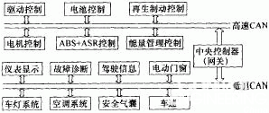
This article refers to the address: http://
Figure 1 System schematic diagram The system is mainly composed of drive control module, regenerative brake control module, motor control module, energy management module, battery control module, instrument display module and fault diagnosis module. Information communication between various control modules is realized by CAN. In addition to the transmission and reception of commands, some basic state information of the car (such as motor speed, battery state of charge, vehicle speed, etc.) is the data that most control units must acquire. The control unit sends data to the bus in a broadcast mode. If all control units send data to the bus at the same time, a data collision on the bus will occur. Therefore, the CAN bus protocol proposes a bus arbitration that uses the identifier to identify the data priority. Table 1 shows the types of data received and sent by the electric vehicle electronic control unit and the procedures for sharing these information with other units.
Table 1 Data types received and sent by electric vehicle electronic control unit
Note: T-Transmit, R-Receive 2. Module Unit Circuit Block Diagram Universal Extension (UDU) is used for hardware design of nodes on high-speed CAN. This simplifies the hardware system design by simply changing the software to implement different functions of each node. The general extension unit structure is shown in Figure 2.
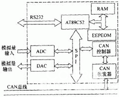
Figure 2 General-purpose expansion unit uses AT89C52 as a microcontroller in the general-purpose expansion unit. It is a low-voltage, high-performance CMOS 8-bit MCU with 8kB of re-writable read-only program memory (EPROM) and 256B random. Access to data memory (RAM), compatible with the standard MCS251 instruction system, built-in general-purpose 8-bit central processing unit and Flash memory unit, suitable for control applications in many more complex systems.
The CAN controller is manufactured by Philips SJA1000, which is a stand-alone CAN controller for automotive and general industrial environments. It has all the necessary features to complete the CAN high-performance communication protocol. The SJA1000 with simple bus connection can complete the physical layer and All features of the data link layer. It can store a complete message that will be sent or received on the CAN bus. It also has a 64-byte extended receive buffer REFIFO. The receive buffer is larger. The microcontroller can continue to receive other messages while processing a message. Message. The bus transceiver uses the PCA82C250, which provides a direct interface between the protocol controller and the physical transmission line, allowing data to be transmitted over two differential voltage bus cables at rates up to 1 Mb/s. The maximum number of attached nodes is up to 110. The PCA82C250 can increase the communication distance, improve the system's instantaneous anti-interference ability, and reduce radio frequency interference. The PCA82C250 and SJA1000 together form the control and interface circuit of the CAN bus.
V. Battery Management Control System Design Battery is a key factor affecting the performance of the vehicle for electric vehicles. It has a direct impact on the performance of the driving range, acceleration performance and maximum grade. The battery control system mainly monitors the working state of the battery (battery voltage, current and temperature), manages the operation of the battery (avoiding over-discharge, over-charging, over-heating and severe voltage imbalance between the cells) to maximize the maximum Take advantage of the battery's storage capacity and cycle life. Its structure is shown in Figure 3.
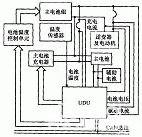
1) Real-time monitoring of the main and auxiliary batteries The UDU collects the battery voltage, current and battery temperature during charging and discharging of the main and auxiliary batteries to monitor the working condition of the battery and perform fault diagnosis.
2) UDU receives the driving state data of the car from the bus, and adjusts the motor speed and power output in real time according to the power demand of the car; when receiving the braking information, the control unit regulates the action of the inverter and the motor, and starts the regenerative braking system to recover the braking energy.
3) Predicting the remaining battery power and the corresponding remaining mileage control unit to predict the remaining power using the corresponding algorithm for the collected charging and discharging current parameters. At the same time, the remaining mileage is estimated using the vehicle speed information received from the bus, and the estimation result is sent to the meter display unit via the bus.
VI. System design Because the temperature range of the car is large (-45~100°C), electromagnetic interference and other electronic noise are strong, and the environment is bad. To ensure the system's operation in the car, it is necessary to improve the network structure itself. Fault tolerance and anti-jamming capability. In the design, the combination of hardware and software is used for anti-interference.
The hardware uses electromagnetic compatibility design, focusing on the interference caused by electrostatic field, magnetic field and transmission line and circuit. It adopts filtering, decoupling, isolation, shielding and grounding to add Power Supply voltage detection, watchdog and other circuits. The specific measures are as follows.
(1) The transmission line is shielded twisted pair.
(2) Timeout reset with the watchdog timer.
(3) An optical isolation circuit composed of a high-speed isolation device 6N137 is added between the CAN controller SJA1000 and the CAN transceiver PCA82C250, and the power supply is also isolated by a micro DC/DC module.
(4) Connect CANH and CANL of PCA82C250 to CAN bus through a 5Ω resistor, which can limit current and protect PCA82C250 from overcurrent impact. CANH and CANL are connected in parallel with a 30pF capacitor, and can also filter the bus. High frequency interference on.
(5) Damage to the transmission medium or damage to the bus driver can damage the CAN communication. If these failures are not automatically detected and the corresponding measures are taken, the system will partially or completely lose communication capability. An effective way to solve this problem is to use redundant communication control to ensure the main function of the communication system to operate normally, thereby improving the system's reliability.
The software adopts the techniques of error and fault tolerance, etc., software filtering the signal, designing the power-on reset anti-interference program, and using the effective insurance technology to design the anti-interference interference program.
VII. Conclusion This paper introduces the characteristics of CAN bus and its application in electric vehicles. It designs the node setting of the electric vehicle control system based on CAN bus, and introduces the universal expansion unit to simplify the system hardware design and the battery that affects the performance of electric vehicles. The management control unit has been optimized. The system has the advantages of compact structure, high reliability, perfect function and low cost, and can better meet the working requirements of electric vehicles.
1) Real-time monitoring of the main and auxiliary batteries The UDU collects the battery voltage, current and battery temperature during charging and discharging of the main and auxiliary batteries to monitor the working condition of the battery and perform fault diagnosis.
2) UDU receives the driving state data of the car from the bus, and adjusts the motor speed and power output in real time according to the power demand of the car; when receiving the braking information, the control unit regulates the action of the inverter and the motor, and starts the regenerative braking system to recover the braking energy.
3) Predicting the remaining battery power and the corresponding remaining mileage control unit to predict the remaining power using the corresponding algorithm for the collected charging and discharging current parameters. At the same time, the remaining mileage is estimated using the vehicle speed information received from the bus, and the estimation result is sent to the meter display unit via the bus.
Step up&Down Transformer,ST Step Up&Down Transformer,TC Step Up&Down Transformer
Normal Size PSU(S Series),Constant Voltage( SMV series) Co., Ltd. , http://www.chpower-supply.com