With the advent of high-power LEDs, the lighting industry is also facing new challenges. LED lifetime and power conversion efficiency have become major considerations in designing LED lighting systems. In order to provide a constant current to maintain the consistency of LED color and brightness, the constant current LED driver can be used as a switching converter that provides a constant current output. In addition, power-saving or high-efficiency power conversion requirements are an indispensable element in LED lighting applications, and hysteresis pulse frequency modulation technology (HystereTIc PFM) can greatly improve power conversion efficiency at light or heavy loads. This article will explore how to design a high-efficiency, high-stability LED lighting system using a constant current LED driver.
Traditional LED Driver: Constant Voltage Mode
The current flowing through the LED determines the brightness of the LED. The higher the current, the brighter the brightness of the LED. In general, the use of a constant voltage or constant current driver can achieve the purpose of lighting the LED. Figure 1 shows the simplest constant voltage LED driver. The current through the LED is controlled by the resistor in series with the LED. For example, if the input voltage is 5V and the forward bias of the LED is 3.6V, then under this condition, if the required LED current is 20mA, the current limiting resistor to be used is 70Ω. Although the architecture of this method is very simple, the LED current will change with the voltage falling across the LED. If the LED forward bias is inconsistent or the input voltage changes slightly, it will affect the brightness of the LED. In addition, the power loss on the current limiting resistor also causes problems of overheating and inefficiency.
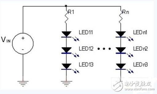
Figure 1: Constant voltage LED driver.
Traditional LED driver: constant current mode
Another commonly used LED driver is a constant current mode driver as shown in FIG. In Figure 2, the current of the LED is provided by a linear regulator whose current can be set by the R1 resistor. Compared to constant voltage mode drivers, constant current mode drivers can control the current flowing through the LEDs without being affected by the LED forward bias and input voltage. However, if the voltage difference between the input voltage and the total forward bias of the LED is too large, there will still be a problem of overheating on the driver.
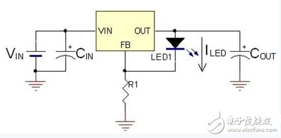
Figure 2: Constant current LED driver.
Hysteresis pulse frequency modulation
The hysteresis pulse frequency modulation control method of the MBI6650 can effectively improve the efficiency of the system in light load applications. Fig. 3 is an application circuit of the MBI6650, and Fig. 4 is a waveform diagram of a hysteresis type pulse frequency modulation method. VSEN in Figure 3 is the voltage drop across the RSEN resistor. The output current of the MBI6650 is determined by this voltage and resistance. VH in Figure 4 is the high level reference voltage inside MBI6650, which is 1.3 times the VSEN voltage and VL is 0.7 times VSEN. The MBI6650 works as follows: When the power is turned on, VSEN is lower than VH, so the built-in MOSFET of the MBI6650 is turned on, and the increase in the inductor current causes the VSEN across the RSEN to increase. When VSEN is equal to VH, the built-in MOSFET turns off, and the inductor current drops through the diode (D1) discharge, causing the VSEN voltage to drop. When the VSEN voltage is equal to VL, the built-in MOSFET turns on again and repeats the previous action. Due to the hysteresis pulse frequency modulation characteristics, the inductor current will remain in continuous conduction mode (CCM), which is very helpful to reduce the LED chopping current.
The switching frequency of this control mode varies with the load current, and the higher the current, the lower the frequency. Under the same load conditions, the larger the inductance, the lower the switching frequency. The switching frequency of the MBI6650 is controlled above 40 kHz to avoid the occurrence of audible noise.
In addition to improving efficiency at light loads, the hysteresis pulse frequency modulation control method has other advantages. For example, due to the use of high voltage current limiting technology, the power loss lost on the current limiting resistor is small, so it can be used. Smaller current limiting resistors help save board space and component cost.
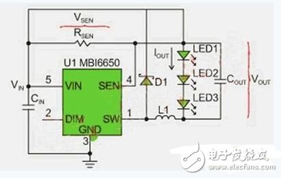
Figure 3: MBI6650 application circuit.
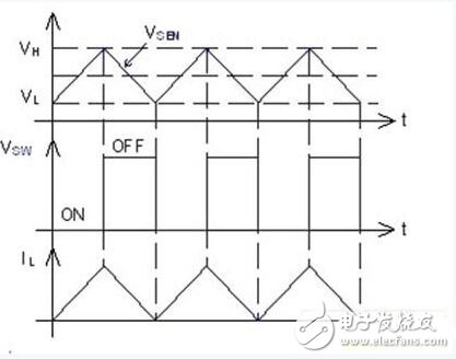
Figure 4: Schematic diagram of the mode of the hysteresis pulse frequency modulation control method.
Protective function
To ensure the safety and reliability of LED lighting systems and drives, the MBI6650 offers several protection features. For example, undervoltage protection (UVLO) prevents the IC from malfunctioning due to insufficient input voltage. It provides hysteresis voltage to avoid noise interference during startup. Open circuit and short circuit protection protects the drive from damage due to fault conditions. At the same time, MBI6650 also provides over temperature protection. When the IC chip reaches 140°C, the IC will automatically turn off the output current to avoid overheating and damage the IC. When the temperature drops to 95°C, the IC will work again.
Summary of this article
When designing a safe and effective LED lighting system, Accumulation Technology's MBI6650 has considerable advantages, such as: hysteresis pulse frequency modulation technology to improve efficiency at light loads, constant current control can improve the use of LED Lifetime and several protection features to ensure the safety and reliability of the lighting system. Compared with traditional LED drivers, the MBI6650's precise output current and high conversion efficiency are more suitable for LED lighting systems.
Lan Transformers For Automotive Battery,Ferrite Core Lan Transformer,Ethernet Isolation Transformer,Pulse Ethernet Transformer
IHUA INDUSTRIES CO.,LTD. , https://www.ihuagroup.com