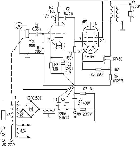
The input stage is dual triode 6N3, and the final stage is 6P1 which is output together with IRF450. Only three electronic tubes are needed for two channels, 6N3 and 6P1 are both peanut tubes, and the market price of IRF450 is also very low.
The magnification of 6N3 is μ = 35, the transconductance gm = 5.9mA / V, common cathode amplification, 6P1 output is about 4W, IRF450 output is 14W, and the common output is 18W. IRF450 can be replaced by other field-effect power tubes, but its reverse withstand voltage must be greater than 500V and power consumption greater than 100W. In this example, when the IRF450 has an operating current of 113 mA, the gate-to-source voltage drop is 3.5 V, so R5 is set to 68 Ω (note that the data for different field tubes will be different and should be measured). If you change the value of R6, you can change the output power of the machine. But if the working current of IRF450 is too large, it is easy to cause self-excitation.
The output transformer needs to be self-made, its core cross-sectional area S = 10cm2, the number of primary and secondary turns is 14: 1, the impedance ratio is 1560Ω: 8Ω, the primary enameled wire ∮ = 0.29mm, around 2100 turns, the secondary wire ∮ = 1,000mm Around 150 turns, you can achieve good results without having to wind in sections. Be careful not to cross the iron pieces. The iron clips or iron laths used to fix the iron core can no longer be used. They must be redone with aluminum plates. Put a layer of kraft paper as the gap layer on the three cylindrical surfaces of the core to ensure that the core does not have any magnetic saturation, so that the transformer distortion can be minimized. The inductance L core cross section S = 9cm2, enameled wire ∮ = 0.33mm, just wrap it up IRF450 uses a larger heat sink to facilitate heat dissipation.
This machine has no large loop negative feedback, good transient response, and simple circuit. It should be noted that the operating current of 6P1 should be 50mA. What needs to be adjusted is the resistance of R6 to determine the final output power.

Follow WeChat

Download Audiophile APP

Follow the audiophile class
related suggestion
The principle of the field effect tube to control the working current is completely different from that of ordinary transistors, which is much simpler than ordinary transistors.

The five-pole power amplifier tube FD422 is used to make a single-ended Class A power amplifier. The design of this circuit is based on the principle of "simpleness first", which can reduce installation errors. Follow first ...

845 single-ended Class A amplifier circuit diagram will be 6N8P
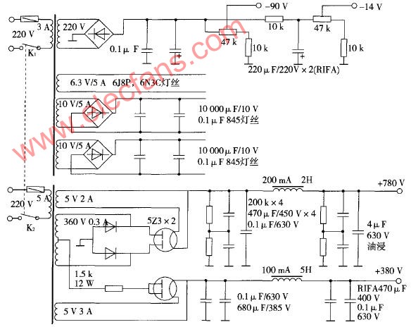
What is a pure Class A amplifier The so-called Class A or pure Class A amplifier is actually two sub-classes of the power amplifier classified by static operating point. According to this division, ...
Field effect tube characteristics and the artistic charm and evaluation of the production of audio amplifiers with single-ended Class A amplifiers Audio amplifiers can be divided into electronic ...
Single-ended Class A power amplifier circuit Below, we introduce a single-ended pure ...
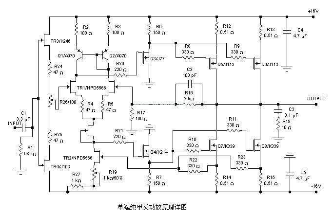
A 20W single-ended pure class A power amplifier circuit diagram, the circuit is very simple, used yuan ...
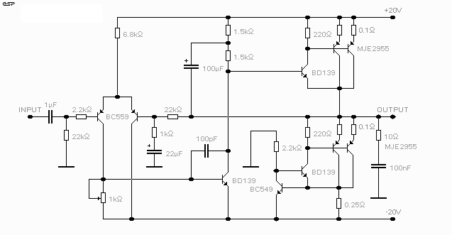
Circuit characteristics 1. This power amplifier uses a current negative feedback circuit (Japan's famous golden voice most power amplifier ...
The power amplifier made with the voltage regulator set is a pioneering idea for electronics enthusiasts ...
![[Photo] NE5532 20W pure class A amplifier driven in parallel](http://i.bosscdn.com/blog/20/06/41/5131158379.jpg)
Many audiophiles are happy to make power amplifiers, but most of them are limited to some single-chip sets such as LM1875, LM3886, LM4766, TD ...