0 Introduction In recent years, the development of digital TV has been very rapid. In August 2007, China officially implemented the nationally-developed national terrestrial digital TV broadcasting DMB-TH standard. Portable products based on DMB-TH standard have become the hotspot of digital TV technology and industry development. The market potential is huge. The USB 2.0 standard was introduced in April 2004, adding a high-speed mode to increase the speed of the USB interface to 480 Mb/s, which is 40 times faster than the original full-speed mode. It extends the application range of the USB interface and enables the USB interface. It is possible to transmit high-speed SD or even HD digital TV.
The USB digital TV receiver bar researched and designed in this paper is a portable device based on USB 2.0 and DMB-TH standard, which can realize the reception of digital TV on devices with USB interface such as laptops and desktops. The digital TV program is played in real time through the corresponding upper layer playing software.
This article refers to the address: http://
1 system overall design
1.1 System Framework The USB digital TV receiver system consists of the following four modules. Figure 1 shows the schematic of the system.
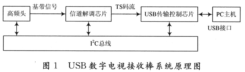
(1) High frequency head: responsible for converting the high frequency signal received by the antenna into a baseband signal and transmitting the signal to the channel demodulator.
(2) Channel demodulator: complete automatic gain control, PN frame header acquisition, channel estimation and equalization, automatic detection and frequency lock, FFT transform, etc., convert the baseband signal into TS stream output, and stream the TS code. To the USB transfer control chip.
(3) USB transmission control module: This module is used as the main control module. After loading the corresponding driver, the initialization and subsequent control of the tuner and channel demodulator are completed through the I2C bus, and the TS code stream is transmitted to the PC. end.
(4) PC-side application software: realizes the reception of the TS stream and plays the program in real time through the player.
1.2 Hardware resources Hardware, because the USB digital TV receiver is a portable device with small size, low power consumption and good mobility, and is aimed at the national standard DMB-TH, so the selected chip must also be special in these aspects. consider. After research, the high frequency head selects Analog Devices' AD-MTV102, and the channel demodulation chip selects the LGS-8GL5 chip of the company. They all support the DMB-TH standard, and the USB transmission control chip selects Cypress's CY7C68013 chip. The hardware system built by the block chip only needs the 5 V voltage of the USB interface to meet its power consumption requirements, and the small size (ordinary U disk size) is easy to carry and fully meets the design requirements of the system.
1.3 Software Resources In software, the core part of the PC-side application is the real-time player. The TS stream needs to be played. This is a code stream defined by the MPEG-2 standard. This program uses a media player based on DirectShow technology. DirectShow is a member of the DirectX family. It provides a complete solution for high-performance multimedia applications such as playback of multimedia files in various formats on the Windows platform, audio and video capture, and importantly, it is well supported. The MPEG-2 standard frees application developers from complex data transfers, hardware differences, synchronization, etc. The overall application framework and underlying work is done by DirectShow, greatly speeding up the development process.
2 hardware driver design Hardware driver is a key part of the system design, it is directly related to whether the hardware chip can work normally and stably. The hardware driver is completed by the main control chip. In this scheme, the uSB transmission control chip CY7C68013 is used as the main control chip. It has an enhanced 8051 core, and controls the front-end tuner and channel demodulation chip through the I2C bus. Complete the driver for the front end.
The hardware driver design is mainly to write the firmware program of CY7C68013 according to the design features of the hardware circuit. The firmware program can process USB standard requests from the system to complete the exchange of various data and transaction processing. CypreSS provides a firmware program framework on which users can add their own function code to perform the functions. The entire hardware driver flow chart is shown in Figure 2.

(1) Set the working mode of the USB chip to Slave FIFO, Au-to In mode, and use Endpoint 2 (set to 1 024 × 4 b size) for transmission. In this mode, the data transmission in the USB chip does not require the intervention of the 8051 core, and the data transmission is automatically completed by using the quantum FIFO unique to CY7C68013, so that the data transmission rate can be guaranteed not to be limited by the frequency limit of the 8051 core. Speed, meeting the requirements of USB 2.0 high-speed transmission.
(2) Turn on the I2C bus, initialize the tuner, and set the scanning frequency of the tuner after delaying for 1 s. Here, the delay of 1 s is to ensure the normal operation of the tuner after initialization, which is the technical aspect of the chip. Claim.
(3) Initialize the channel demodulator and set it to the automatic mode, so that it automatically detects the signal parameters and feeds the information back to the tuner, and coordinates some parameters (such as gain) between the two chips. The two work together.
(4) Determine whether the signal is locked. If it is not locked, then judge whether it is the first time to lock the frequency. If the frequency has not been locked before, you need to change the scanning frequency of the tuner and detect it again until it is locked. If you have ever locked the frequency, you don't need to change the frequency, you can automatically detect it again.
(5) After the lock signal, the lock condition is detected again every 5 s, and if the lock is lost, the fourth step is returned to perform the test again. The purpose of the loop judgment signal lock condition is to prevent the system from malfunctioning due to the loss of the signal quality due to the deterioration of the signal quality during normal operation (for example, the system enters the tunnel and other environments when receiving the system), and the timing detection signal lock condition can be After such an event occurs, take the necessary actions to get the system back to work.
3 PC application design
3.1 Main functions of the application The PC application is a platform for the user to interact with the underlying resource information. In this scenario, the application mainly accomplishes the following two major functions.
(1) Receive the TS code stream transmitted by CY7C68013 from the USB port and store it in the buffer. This function is relatively simple, using the universal driver provided by Cy-press and some corresponding API functions, after opening the USB device to obtain the device handle, set the amount of data read each time, and then open a thread to read the data. , you can continuously get the TS stream. The amount of data read each time has a great influence on the smoothness of playback. In this scheme, the parameters are set to 1,024 B, 8 192 B, 10 240 B, 30 720 B, 61 440 B, etc. Test comparison shows that the larger the value of the parameter, the better the playback effect, which directly affects the packet loss rate. In the end, the program sets the value to 61 440 B, which is also the maximum value that can be obtained by the actual measurement. Under this parameter, the program plays the best effect.
(2) Set up a real-time media player to decode and play the received TS stream. This is the core part of the PC application. There are two ways to choose a real-time media player strategy: one is to use the open source player to modify, but most open source players are written on the Linux platform, to be used under the Windows platform need to be transplanted Only after transplantation, the workload is very large, and the stability of the player after transplantation is difficult to control. The other is to write the player on its own based on DirectShow technology. DirectShow is a member of the Microsoft DirectX family and has a natural "blood" relationship with Windows. It is the best choice for building a media player on the Windows platform. And Microsoft provides the corresponding development kit, which reduces the development workload and shortens the development cycle. Based on the above reasons, this solution chooses to build a real-time media player based on DirectShow technology.
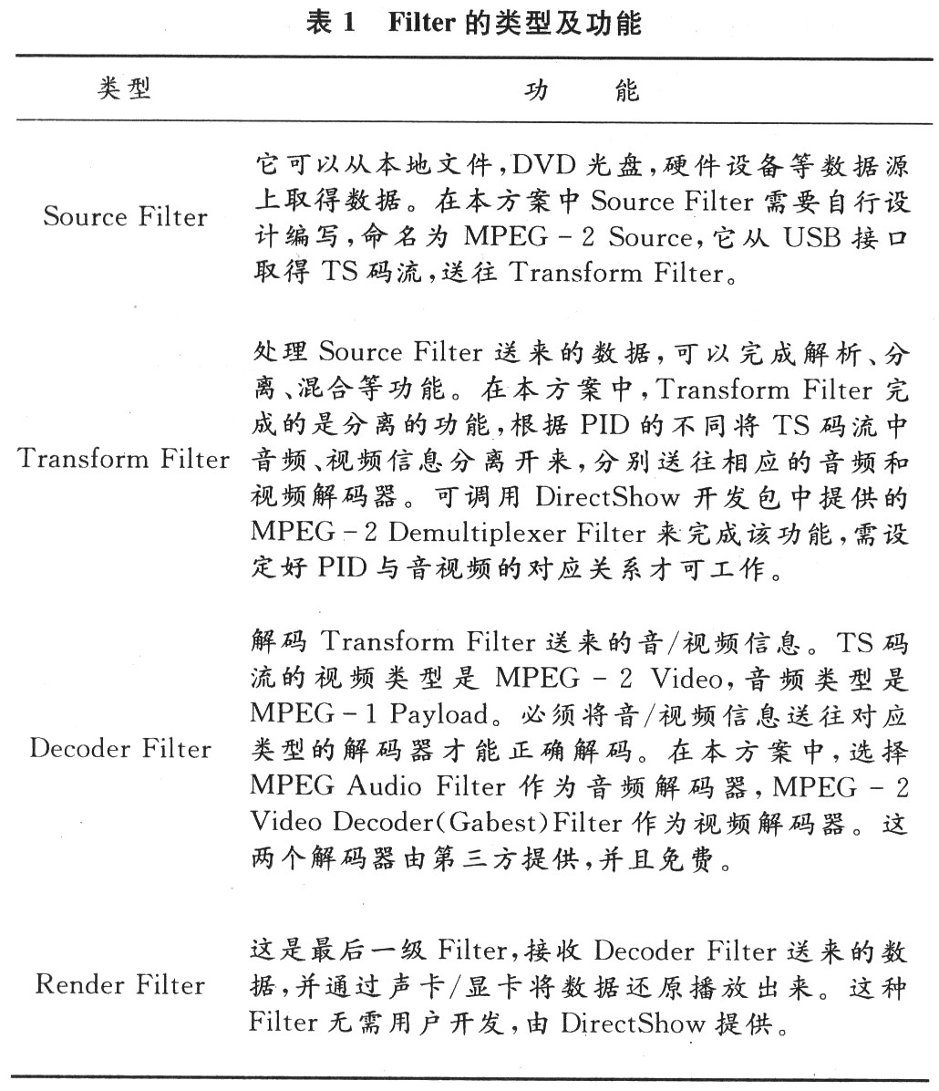
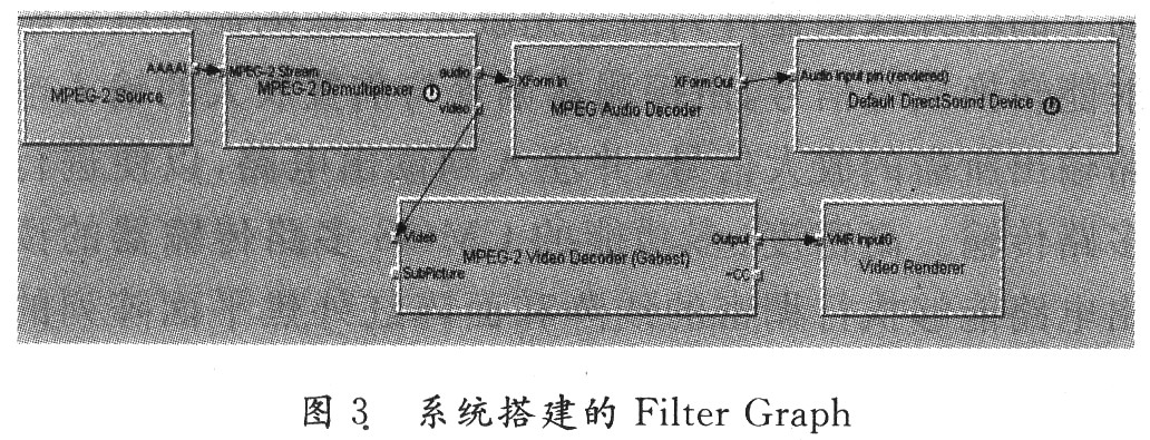
3.2 Application of DirectShow technology in the system In DirectShow technology, a player is connected by multiple Filters with different functions. These Filters do not work independently, but are related to each other and cooperate with each other. It is an organic whole. The whole is called Filter Graph. Filter is generally divided into the following categories, as shown in Table 1.
The Filter Graph built by this system is shown in Figure 3.
4 Experimental results After completing the overall scheme design of the USB digital TV receiving rod system, according to the selected chip, refer to the corresponding technical manual, design the circuit schematic diagram and make the printed circuit board. During the hardware production, the software development work is carried out at the same time. After the hardware was completed, debugging was performed using KEILC and VC6++. The laptop was tested for a long time (12 h) in indoors and in motion, and the speed at which the USB port received data was stable at 1.8 MB/s. The parameters of the national standard DMB-TH digital TV in Xiamen are shown in Table 2.

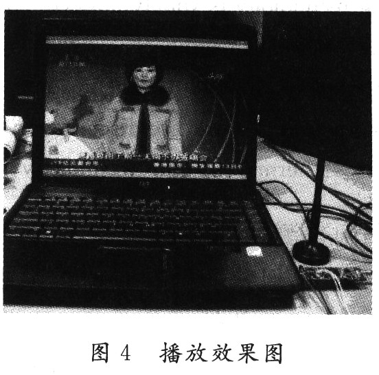
The experimental results show that the whole system works stably for a long time under static and motion conditions, with small volume, low power consumption, good receiving effect, low bit error rate, synchronized audio and video, clear and smooth program playback, and channel switching less than 1 s. Meet the design requirements. The playback effect is shown in Figure 4. The playback channel is Xiamen Satellite TV. The lower right foot of the figure is the USB digital TV receiver and the matching antenna.
5 Conclusion This article first introduced the overall design of the USB digital TV receiver, and then introduced in detail the two key points of the system implementation - the design of the hardware driver and the design of the PC host application. With the implementation and promotion of the national standard DMB-TH standard, the increase of terrestrial digital TV programs in various places, USB digital TV receiver as a portable, hot-swappable digital TV receiving equipment will be favored by people, practical value and market prospects. I am optimistic.
Washing Machine Motor,Spin Motor Of Aluminium Wire,Washing Machine Motor Shaft,Automatic Washing Machine Spin Motor
WUJIANG JINLONG ELECTRIC APPLIANCE CO., LTD , https://www.jinlongmotor.com