Three-phase AC motors such as permanent magnet synchronous motors (PMSM) and induction motors have long been widely used in industrial control systems. In automotive applications, these motors are relatively new and are now being used as supplements or replacements for conventional internal combustion engines. The windings used in PMSM are three-phase sinusoidal distributed windings and mechanical displacement windings. A three-phase sine wave and a time-displacement current can generate a rotating magnetic field. This rotating magnetic field causes the motor to rotate and is generated by switching the current in the motor windings through a MOSFET (in the inverter). The Field Oriented Control (FOC) algorithm generates a PWM mode for motor current control. The position and current of the rotor are continuously detected. Efficient FOC systems based on high-performance microcontrollers create the conditions for safe and efficient solutions for electric and hybrid vehicle drives (Figure 1).
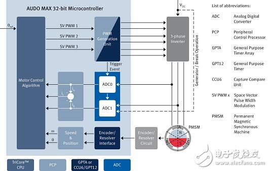
Figure 1: A 32-bit TriCore microcontroller running in FOC mode.
PWM generation method for AUDO MAX product line
Infineon's 32-bit AUDO MAX family of microcontrollers houses a main core (TriCore CPU, light green) and a fast coprocessor (called PCP, dark green). This asymmetric architecture enables PCP to efficiently process peripherals without disrupting the processing of the main algorithm running on the TriCore CPU. The PCP handles critical real-time interrupt loads, thus reducing the CPU load.
There are two ways to generate a PWM.GPTA that drives the inverter to generate very complex PWM modes, such as asymmetric dead time generation or custom mode. The peripheral module CCU6 is a low-end solution that can be used to generate center-aligned and edge-aligned PWM modes. Compared to GPTA, CCU6 can directly support PWM signal generation with low software overhead, and there is no need to configure multiple timer units.
Both the CCU6 and GPTA modules have a trigger function that allows PWM signals and A/D current measurements to be isochronous without delay (see arrow "Trigger events"). As an added safety feature, each GPTA module is equipped with an "emergency mode stop signal" that can be used to set a safety switch. For all members of the TriCore AUDO MAX microcontroller family, a PRO-SIL-based security platform is provided that includes hardware (safety watchdog CIC61508) and software (SafeTcore driver) to meet ASIL-certified Class B to D Level requirements.
Current measurement through an analog-to-digital converter (ADC)
The example given in Figure 1 measures the two phase currents of the motor and converts it using an analog to digital converter. Based on the successive approximation register (SAR), the analog-to-digital converter has high accuracy (12-bit resolution) and a conversion time of less than 1 microsecond. The third phase current can be calculated from two known phase currents. For higher safety requirements, it is recommended to make additional measurements on the third phase current of the motor. For this application, a microcontroller with a third analog to digital conversion module is available.
Connecting the resolver and encoder
The resolver converts the angular displacement of the PMSM rotor into an electrical value. In general, an additional tangent function circuit can be used to derive the angular value of the rotor from two signals (sine/cosine). The signal from the resolver circuit is output to the SPI bus, and the sine and cosine signals of the resolver can also be directly read by the microcontroller. An alternative is to read the encoder signal, condition it in the encoder interface running on the microcontroller GPT12, and feed it back to the control algorithm.
Reuse of automotive electronics software outside of AUTOSAR
In recent years, automotive electronic software and communications have been standardized through specifications such as OSEK, AUTOSAR, and FlexRay. In addition to standardized software components, automotive electronic systems use control algorithms that can be reused in a variety of applications. Today, motor control is accomplished by electronic control units (ECUs) distributed throughout the car body, chassis, and powertrain systems. The MC-ISAR eMotor driver extracts the general characteristics of current control in three-phase motor applications and is designed to support multiple position information acquisition modes and inverter control devices.
Three-phase motor control
The Infineon AUDO MAX series is ideal for motor control. TriCore architecture and MC-ISAR eMotor drivers can control multiple three-phase motors with advanced control strategies, including brushless DC motor (BLDC) block swap (block commutaTIon, BC) and permanent magnet synchronous motor (PMSM) field oriented control (FOC) ). A single microcontroller can even support both BLDC and PMSM motor control. Compared to other types of motors, FOC-controlled PMSM motors offer higher energy efficiency, lower wear and precise control and positioning. In particular, this motor supports linear torque control and lays the foundation for its use in hybrid electric vehicle powertrain systems.
Figure 2 shows the current control loop for the MC-ISAR eMotor driver and the complex device driver (CDD) on the right. This time critical current control loop is processed in the interrupt context with a processing time of no more than 50 microseconds. On the left is an additional software component (SWC) for position and speed control, provided by the application.
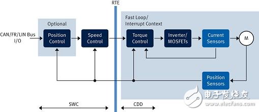
Figure 2: Current control loop in motor control.
Position detection and current detection mode
In order to meet the requirements of precise positioning, MC-ISAR eMotor achieves a typical high-resolution detection mode by using a Hall sensor plus an incremental encoder and a resolver. In addition, sensorless FOCs can also be used in fail-safe mode. For cost-sensitive applications, the AUDO MAX series supports direct resolver mode, which is implemented in software and discrete components, eliminating the need for an external resolver IC, which reduces the cost per control unit by around $2. . At the same time, the MC-ISAR eMotor can support two-phase or DC bus current measurement mode (Figure 3).
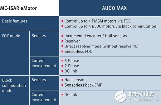
  Figure 3: MC-ISAR eMotor operating mode.
MC-ISAR eMotor software division
This software can be divided into two components: hardware-independent and hardware-dependent components. Hardware-independent modules are used for EmoControl, location information collection PA, and FOC (Figure 4). Therefore, EmoControl is the main module for controlling direction and current through FOC. The current delivered to the motor determines the torque. The MC-ISAR eMotor driver feeds back the motor position and speed information to the application. The position information acquisition PA module is responsible for extracting angle information from the resolver and encoder signals. A FOC with Park-Clarke Transform and Space Vector Modulation (SVM) is the main part of setting up a new current by detecting a given current and position.
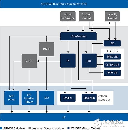
Figure 4: Block diagram of the Field Oriented Control (FOC) module.
Hardware-related modules, including reusable AUTOSAR MCAL drivers (ADC, SPI, DIO), or dedicated modules for PWM signal generation (EmoPwm driver CCU6) and encoder interface EmoIcu (read coded signals via GPT12). The position and speed control codes written by the customer can be added as standard software components (SW-C), as provided by AUTOSAR.
MC-ISAR eMotor security considerations
To support applications that meet security requirements, it is important to consider security requirements when designing software components from the start. The specific needs of the application should be clarified during the development phase of the ECU, and these requirements will vary from application to application. In addition, to support safety applications, certain safety factors for off-the-shelf motor drives should also be considered. The MC-ISAR eMotor was developed using an ISO26262-compliant software development process and supports three-phase current measurements in safety-related systems.
Overview of the main advantages of Infineon eMotor
Infineon's AUDO MAX series and MC-ISAR eMotor drives control up to four PMSM or BLDC motors in parallel while meeting the performance required for application task control. The MC-ISAR eMotor and the standard AUTOSAR MCAL driver are integrated by the same configuration tool, so users can configure microcontroller resources for the AUTOSAR MCAL and MC-ISAR eMotor drivers in the same interface, creating the conditions for seamlessly configuring different software modules. Automotive ECU developers can focus on application-related control of the motor without having to adapt the motor's control algorithms. To reduce system cost, the AUDO MAX series also supports direct resolver mode, eliminating the need for a rotary transformer IC. The AUDO MAX series and MC-ISAR eMotor drivers are designed to support safety applications.
Technical features
1. Preeminent effects: Clear and stable pictures without distortion and disturbance.
2.
quality: adopting first-class chips and wafers imported from abroad
3. Flexible form: continuity, overlying, combination of dynamic and static playing, various effects include rolling moving, typewriting, gradual changing and so on
4. off-line running function: adopting the monolithic design technology and computer string communication way, which can operate in off-line state setting the dates and revising a data via the telephone line
Technical Parameters
Multi language: English/Spanish/Russia/Inter.char.set-..
1)High Brightness, user can change the advertising words whatever you want, easy and convenient in operation, more attactive compared with traditional banner.
2) The led moving sign display supports many kinds of languages and characters.
3) A lot of lively animation icons are built-in. 50 and more action effects for user option; Different brightness can be adjusted in software.
4) Time clock format, support date, countdown and any other odditional functions like temperature and humidity. Voltage input: 220v or110v.
5) led moving sign display Structure: well appreance frame, professional pendents, standard connectors and other accessories.
Usage
Service propaganda in finances, post offices, telecom, commerce, hospitals, sports stadiums
Policies and decrees issued from government organizations
Instructions, guidance and information issuance in airports and railways
Our service
1.Your inquiry related to our products or price will be replied in 24hrs
2.OEM&ODM,any your customized lightings we can help you to design and put into product
3.Protection of your sales area,ideas of design and all your private information
4.Top Quality+Reasonable Price+Responsible After Service=Successful & Win
5.Produce all kinds of Pitch: P4.75, P7.62, P10, P12, P16, P20, P25, P31.25...

Indoor Single Color LED Display
Indoor Single Color Led Display,Led Panel Screen,Single Led Display,Single Color Led Message Display
Shenzhen Joy LED Display Co., Ltd. , https://www.joe-led.com