Abstract: The vehicle remote anti-theft system based on STM32F103R6T6 single-chip microcomputer is designed. The application of the WT588D voice module adds the folding and unfolding function of the rear view mirror to make the anti-theft more intelligent. Combined with the internal structure of STM32F103R6T6, the hardware circuit of the system is designed, and the software design method of the system is introduced in detail. The experimental results show that the system can effectively process the detected abnormal conditions in real time and drive the voice module to make correct voice reminders.
Key words: STM32F103R6T6; automobile; anti-theft; WT588D
Introduction In recent years, more and more car theft cases have caused huge economic losses. A variety of car alarms have appeared on the market. The car anti-theft system uses STM32F103R6T6 (hereinafter referred to as STM32F103) single-chip microcomputer produced by ST Company as the controller, which has powerful functions and good real-time performance.
1 System structure and function The vehicle remote anti-theft system is designed based on modern wireless communication technology. It can transmit the state information of the car directly to the owner's mobile phone without the constraint of distance. The one-to-one anti-theft alarm is used. The structure of the car remote anti-theft system is as follows. Figure 1 shows.
This article refers to the address: http://
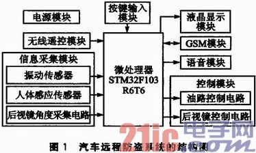
The information collection module of the car anti-theft system includes a human body sensing sensor, a vibration sensor, etc., for collecting car alarm information. The sensor will collect the alarm information, send it to the microprocessor for processing, and the microprocessor will start the alarm program. First, send a text message to the owner's mobile phone; then, the alarm will give a voice warning according to different alarms. For example, if someone enters the car, the alarm will send a voice alarm "You have entered the car, please leave."
The owner can send instructions to check the status of the car at any time.
When the anti-theft device is armed, the system controls the rear view mirror to fold; when disarming, the rear view mirror is controlled to expand.
The liquid crystal display section is used to display the angle value set by the owner.
The wireless remote control is used to arm and disarm.
2 system hardware design
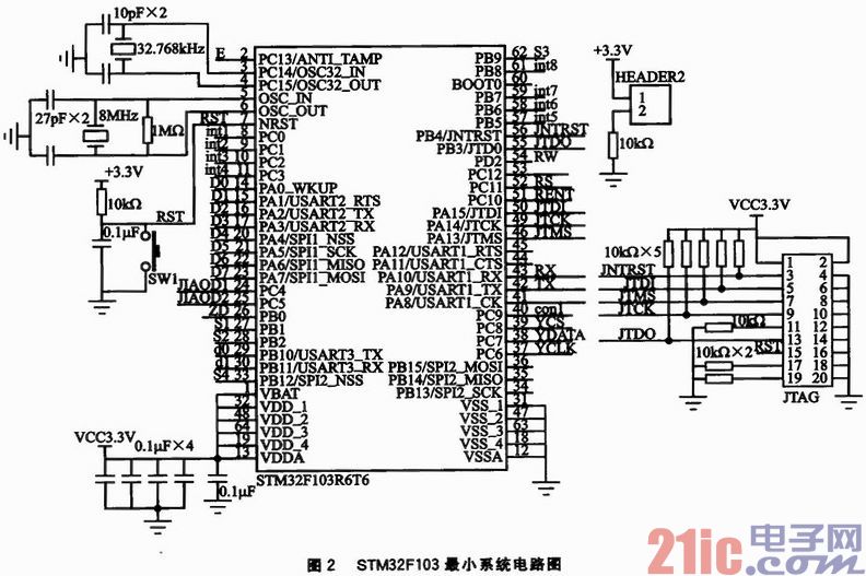
2.1 MCU minimum system STM32F103 minimum system shown in Figure 2, consists of STM32F103 microcontroller, crystal oscillator circuit, JTAG interface and reset circuit. The STM32F103 enhanced microcontroller is based on the high-performance ARM Cortex-M3 (32-bit RISC core) with 32 KB Flash and 10 KB SRAM, 64 enhanced I/O ports, and 2 USARTs. The STM32F103 is available in a 64-pin LQFP package with a supply voltage of 2.0 to 3.6 V. The power-saving mode guarantees low power consumption and is cost-effective. The MCU uses 32.768kHz and 8MHz external crystal oscillators to provide accurate clock source and working clock respectively; the reset circuit is designed as a combination of button reset and power-on automatic reset. The application of the STM32F103 chip improves the execution efficiency of the entire system, enhances system stability, and reduces power consumption and production costs.
2.2 Information Collection Module The information acquisition module mainly includes human body induction sensor, vibration sensor and rear view mirror angle acquisition circuit. The human body sensor mainly detects whether a car thief enters the car for theft, and the data output terminal is connected to the PC10 pin of the single chip microcomputer. When the car is bumped, smashed, shaken, or pulled, the vibration sensor detects the relevant information and sends it to the PB0 pin of the microcontroller for processing.
In the car anti-theft system, the PC4 and PC5 pins of the STM32F103 receive the input data of the left and right angle sensors respectively. The A/D conversion function of the PCA and PC5 pins converts the analog voltage into digital quantities and displays them on the LCD1602. .
2.3 GSM module
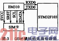
The GSM module uses Huawei's EM310. EM310 GSM supports serial interface, serial communication with the outside world through UART interface, and RXD0 and TXD0 pins of STM32F103 microcontroller are connected, controlled by AT command. The UART supports programmable data widths, programmable data stop bits, programmable parity, or no parity. Supports up to 115.2 kb/s and supports a baud rate of 300 b/s. It supports a rate of 9 600b/s by default and supports baud rate power-down save. The GSM module has a standard SIM card interface, and the GSM module connection circuit diagram is shown in Figure 3.
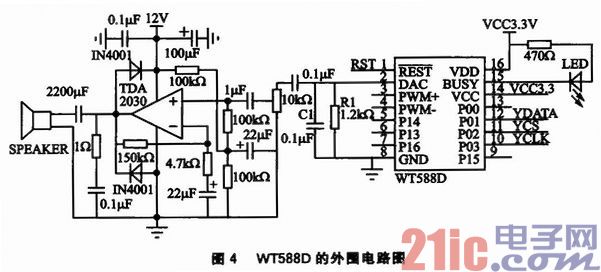
2.4 WT588D voice module This system uses WT588D voice module with 32 Mb memory. When recording at 8 kHz, the recording time is up to 790 s, which meets the requirements of voice reminder. In the alarm system, the voice reminder needs a higher decibel. In order to drive the high-powered speaker, the output is in the form of a DAC-connected power amplifier. The circuit diagram of the WT588D voice module is shown in Figure 4. R1 and C1 are connected in parallel to the ground power amplifier. The power amplifier is TDA2030, rated at 14 W, cost-effective and widely used. The connection between the voice module and the single-chip microcomputer adopts the 3-wire serial port control mode. Unlike the standard 4-wire SPI, the WT588D only receives the data, command and clock signals sent by the single-chip microcomputer without transmitting data. In this 3-wire serial port mode, P01 is the DATA data interface, P02 is the chip select CS, and P03 is the CLK clock, which is respectively connected to the PC7, PC8, and PC6 of the single chip microcomputer. The module supply voltage is 2.8 ~ 3.6 V, 3.3 V is selected. BUSY is the busy signal output. When the output is low, the LED is on, and it is in the playback state. The WT588D module has a wide range of applications and can be applied to almost all voice applications, such as station, alarm, alarm clock, smart home appliances and other automatic control applications.
2.5 Control Module Design
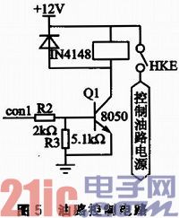
2.5.1 Oil circuit control circuit The specific method for controlling the automatic power-off of the gasoline injection system power supply is to install a normally closed type vehicle power-off relay on the power line of the gasoline injection system to control the power supply of the gasoline injection system. The oil circuit control circuit is shown in Figure 5. R2 and R3 function as current limiting. When con1 is high, Q1 is turned on, and the relay is turned on, thereby achieving power-off and flameout. Under normal circumstances, when con1 outputs a low level, Q1 is turned off, the relay is closed, and the fuel injection system power supply circuit is turned on. When the relay coil is turned off, it will induce a large self-induced electromotive force and easily break through the transistor 8050. Therefore, the diode IN4148 is reversely connected in parallel across the relay to absorb the electromotive force and protect the triode.
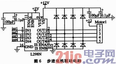
2.5.2 Rearview Mirror Control Circuit Each rearview mirror is controlled by a stepper motor and two buttons. The stepper motor is used to rotate the rearview mirror. The two buttons are the angle increase button and the angle decrease button. According to their own habits, the owner uses the buttons to set the angle of the mirror. When the system is armed, the rear view mirror is controlled to be folded; when disarming, the rear view mirror is controlled to expand. Figure 6 is a drive circuit for controlling the angle of one of the mirrors.
The chip L298N has two power sources, which are working power and driving power. VSS is the working power supply, the voltage range is 4.5 ~ 36 V, the system selects 5 V working voltage; VS is the driving voltage,
The maximum is 36 V, and the VS is preferably better than VSS. The design uses 12 V. Int1, int2, int3, and int4 are the input terminals of the single-chip control motor, which respectively correspond to the four outputs of OUT1, OUT2, OUT3, and OUT4, and the output is connected to the four-phase five-wire stepping motor. ISENA and ISENB are the enable terminals and directly connect to the 5 V logic power supply. That is to say, both motors are always enabled. Since the motor we use is coiled, a sudden reverse current is formed when the operating state suddenly switches to the stop state and suddenly changes from the clockwise state to the counterclockwise state. The function of adding a diode to the circuit is When the reverse current is generated, the flow is discharged to protect the safety of the chip. Motorl provides sockets for stepper motors.
2.6 Wireless remote control module The remote anti-theft system of the car does not require the owner to contact the anti-theft device at a close distance, and uses the wireless remote control to arm and disarm the system. When the owner is at the time, the anti-theft system is disarmed to avoid misjudgment. After the owner leaves, the vehicle can be fortified. The wireless remote control module uses the codec chip PT2262/PT2272 produced by Pucheng, Taiwan, and the working voltage range is 2.6~15 V. The remote control transceiver module is shown in Figure 7.
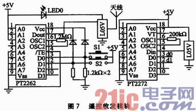
The transmitter PT2262 sets two buttons S1 and S2 to respectively arm and disarm the system. When S1 is pressed, the D0 pin of PT2262 is input high level, Dout transmits code to PT2272; the D0 pin corresponding to PT2272 of the receiving end outputs low level, the MCU detects that d0 is low level, the system enters the forcing state, each The module starts working. The data output d0, d1 of PT2272 is connected with PB10 and PB11 of the single chip microcomputer. Each time a button is pressed, Dout will output the same code in the same system. The MCU will realize the user's arming and disarming requirements according to the detected data output pin low level of the receiving module.
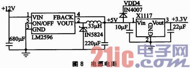
2.7 Power Module The power supply voltage of the car is +12 V. The voltage required by each module in the system is +5 V, +3.3 V and +4 V. Therefore, it is necessary to convert the +12 V voltage into a power conversion circuit. +5 V, +3.3 V and +4 V voltage. The +12 V is converted to 5 V using the LM2596 switching voltage regulator, which has a fixed voltage output and an adjustable voltage output. The +5 V fixed voltage output is used here, and the output current is up to 3 A. It has overheat protection and current limit protection. Based on the output of +5 V, the X1117 regulator is used to convert the +5 V voltage to +3.3 V. X1117 is a low voltage drop three-terminal linear regulator circuit with positive voltage output. It can output fixed voltage +1.5 V, +2.8 V, +3.3 V, etc. It can also output adjustable voltage. The input and output voltages of the X1117 should not be too different to prevent damage to the device due to excessive heat dissipation. The system depressurizes the voltage from +5 V through diode IN4007 by approximately 0.7 V to obtain the voltage required by the EM310 module. The power supply circuit is shown in Figure 8.
3 system software design system uses C language to write the program, write the program to the single-chip computer, can carry out system test. This design writes the source code of STM32F103 in the MDK compilation environment, which is generated after compilation. The hex program code, using the JTAG download line will. The hex file is downloaded to the Flash of the target microcontroller.
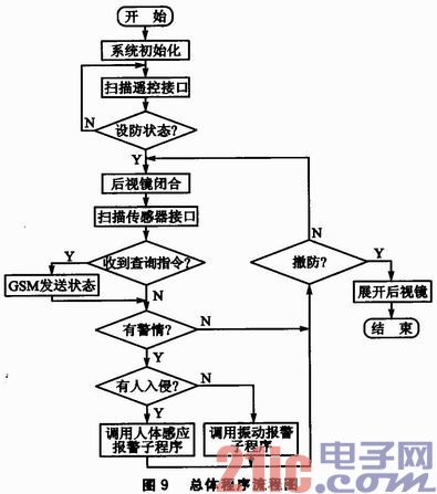
The overall program flow chart of the system is shown in Figure 9. After the main controller STM32F103 is initialized, the system detects whether it is in the armed state. The remote control PT2262/PT2272 does not require software coding. It only needs to detect whether the receiving module has received the arming control. If the system is not armed, the program performs a loop that controls the mirror and scans the remote interface. If it is in the armed state, the control mirror is closed and folded, and the system keeps monitoring the human body sensing module, the vibration module and the controller interface to collect the alarm information at any time. If the owner queries the status of each interface through SMS, the program calls the GSM communication program to send the status of each interface. If there is an alarm, by detecting the interface of the microcontroller, it is judged whether the car is vibrating or someone illegally invaded. Then, according to different situations, the human body induction alarm subroutine or the vibration alarm subroutine is called to perform corresponding processing, and then the single chip scans the remote controller interface to decide whether to continue to arm or disarm. If disarmed, the mirror expands to the angle set by the owner.
Conclusion This paper completed the overall design of the vehicle remote anti-theft system based on STM32F103 MCU, and designed the software and hardware of the system. After trial and error, the system basically met the expected requirements.
- STM32 microcontroller Chinese official website
- STM32 microcontroller official development tools
- STM32 microcontroller reference design
Piezoelectric Ceramic Ring
Applications: ultrasonic vibration tranducer for inkjet printer
Vibration mechanism of inkjet printer:
Generally, it is composed of piezoelectric ceramics and driving rods. By high-frequency electric excitation, piezo ceramics produce high-frequency ultrasonic vibration (above 60 kHz or higher), which is transmitted to the driving rod and generates high-frequency micro-displacement (back and forth expansion) at its front end.
Piezo ceramics components features :
1. High vibration amplitude and can withstand higher power.
2. The product has high reliability, strong maintainability, and is not easy to break down or off-line.
3. The frequency can be adjusted in a wide range, generally within the range of 10KHz.
Yuhai support all the new developping transducer, Welcome the customized elements inquiry.
The present Piezoelectric Elements For Inkjet Piezo Transducer is following :
Piezo rings OD4*ID2*2.5mm price USD1.20/pc, 2000pcs
Material: PBaS-4
Fr.: 694 KHz ±5KHz
K33: ≥0.55
Tg loss <0.5%
Ct 60pF ±12.5%
Piezo rings OD4*ID2*2.5mm price USD1.20/pc, 2000pcs
Material: PSnN-5
Fr.: 626KHz ±5KHz
K33: ≥0.57
Tg loss < 2%
Ct 53pF ±12.5%
Piezo rings OD6*ID2.5*2mm price USD1.50/pc, 2000pcs
Material: PZT-41
Fr.: 785 KHz ±5KHz
K33: >0.53
Tg loss < 0.5%
Ct 107 pF ±12.5%
Piezo Rod OD3*7mm price USD1.20/pc, 2000pcs
Material: PLiS-51
Fr.: 192 KHz ± 3KHz
K33: >0.62
Tg loss < 2%
Ct 18.7 pF ±12.5%
Piezoelectric Elements For Inkjet Piezo Transducer
Inkjet Piezo Transducer,Piezoelectric Vibration Tranducer,Piezoelectric Rings,Piezoelectric Elements For Inkjet Piezo Transducer
Zibo Yuhai Electronic Ceramic Co., Ltd. , https://www.yhpiezo.com