Ripple and noise

Ripple
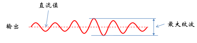
â– The output of the switching power supply is not truly constant. There is periodic jitter in the output. These jitters look like ripples and are called ripples.
â–¶ Ripple can be voltage or current ripple.
â– Ripple is usually described with 2 parameters:
â–¶ Maximum ripple voltage: The peak-to-peak ripple.
â–¶ Ripple factor: The ratio of the effective value of the AC component to the DC component.
Causes of ripple
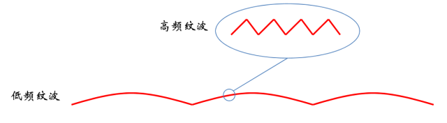
â– The ripple of the switching power supply comes from two places:
â–¶ Low-frequency ripple: The period from the AC input, the power supply's rejection ratio to the input is not perfect, when the input changes, the output will change.
â–¶ High-frequency ripple: The period from the switching of the switch, the switching power supply is not a linear continuous output energy, but the energy is formed into a package to transmit, so there will be ripple corresponding to the switching cycle.
â– If it is a linear power supply, there is no switching ripple, only low-frequency ripple.
Effect of ripple
â– The maximum ripple will determine the peak value of the output. The original output is a stable voltage or current. Due to the influence of ripple, the peak value of the output is higher than the average value, which may damage the load.
â–¶ For example, for LEDs, excessive current will reduce the lifetime of the LED.
â– Excessive ripple factor can make the output energy unbalanced and smooth, thus deviating from the requirement of DC output.
â–¶ For example, for an LED, an excessive ripple factor causes the LED brightness to change, causing flicker.
â– If the switching power supply is used to drive the battery, the load of the LED lamp is more affected by the low-frequency ripple. If it is a high-speed load such as a driver IC, the high-frequency ripple has a greater effect.
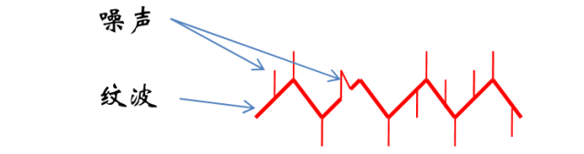
Ripple and noise
â– Ripple is the output jitter caused by the AC cycle or switching cycle, and the noise is a high-frequency signal that is randomly coupled to the output and is not the same.
Adjustment rate

Adjustment rate
â– When the power supply is in use, there are two distinct external conditions: input and load. A good power supply should maintain constant voltage or constant current when the input and load changes.
■When the input or load changes, the degree of output deviation from the rated output is called the adjustment rate, for example, the input changes between the maximum and minimum, the measurement output deviation ratio is a percentage, such as 5%, referred to as the adjustment rate ± 5%.
â– Note the difference between regulation and ripple. Ripple is the dynamic characteristic of the output, while regulation is the limit deviation of the output when the power supply is operating under the extreme external conditions.

Adjustment rate type
â– Input adjustment rate
â–¶ Other conditions remain the same. When the input is adjusted, the output deviation is AC line voltage, which is the variation of the AC line voltage. For example, the upper limit and the lower limit of 180 to 264 change.
â–¶The frequency of the AC is sometimes adjusted to see if there is any deviation in the output, for example from 47 to 63Hz.
â– Load regulation
â–¶ Other conditions remain unchanged, and the output deviation when adjusting the load.
â– Comprehensive adjustment rate
â–¶ Adjust the input and load simultaneously to find the worst deviation.

LED constant current drive
â– Why are lighting LEDs all current driven?
â–¶ LED is a diode, and the forward conduction impedance of the PN junction of the diode is a negative temperature coefficient. As the temperature increases, the forward conduction resistance of the diode decreases.
â–¶If you use a constant voltage source to drive the LED, the temperature starts to rise as the LED works, and after the temperature rises, the forward conduction resistance decreases, due to I=U/R, the current increases, and because of the power P=U*I, The power is also increased, LED fever is more severe, further stimulate the temperature rise, trapped in a vicious circle until the LED is damaged.
温度 When driving with a constant voltage source, the temperature and the circuit are a pair of positive feedback.
â–¶ Therefore, the lighting LED is driven by a constant current. If it is not illuminated, the LED has almost no temperature rise, and at this time, it can be driven with a constant voltage.
Constant current accuracy
â– The constant current accuracy is the same as the constant pressure effect of other movies and is reflected in several aspects.
â–¶ When the load changes, the power output current is constant.
In practice, multiple different LED strings cannot have the same impedance characteristics. After these different loads are connected to the power supply, the current error is defined as the constant current accuracy.
â–· is not only a multi-load, the same LED, when the temperature is different, the impedance characteristics are also different, the current at different temperatures is also error, but this is still the same as the previous conditions, are all load changes.
Therefore, when testing constant current accuracy, you need to use an electronic load to allow the load to change within a reasonable range and measure the current error of the voltage.
â–¶ The constant level of current output by the power supply when the internal component parameters of the power supply change.
â–· This is not the definition of the standard constant current accuracy, but many current power supplies have this requirement. One of the important indicators is the energy storage components, such as inductors, or transformers. When there is an error in the sense of value, the output current of the power supply is constant. .
â–· Considering the cost factor, the deviation of energy storage components during processing is very large. Therefore, the power supply should be designed to be insensitive to the inductance of the energy storage components.
Lithium battery constant current drive
â– Lithium batteries used in portable devices have different voltages under different power conditions. Take lithium batteries used in mobile phones as an example. The battery is about 4.2V at full power and about 2.5V at low power.
â– If you use a constant voltage source to charge the battery, when the battery is running low, the charging current will be extremely high, which means that the voltage source is connected to the capacitor and can damage the battery.
â–¶ The cause of the damage is the large heat generated by the large current.
â– In order to limit the large current, current chargers use constant current-constant voltage charging. When the battery voltage is low, constant current output is used.
Impact and Surge

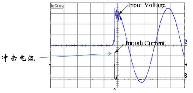
electric shock
â– If the load is a capacitive load, when a voltage source is directly applied to the load, a very large current is generated. This current is called inrush current.
â–¶ Excessive inrush current will cause the protection circuit on the AC line to be identified as a short circuit, which will cause the air switch to trip and blow fuses.
â– For an AC power supply, the AC power supply itself is a capacitive load when the power supply is connected to the AC line. If the load of the power supply is at full load and the AC line is at the peak voltage, it will Produce the largest inrush current.
Surge (voltage)
â– Lightning, lightning strikes, etc. will create very short high-voltage pulses or high-energy pulses on the grid.
â–¶The overvoltage is usually protected by a special protector, such as a surge arrester.
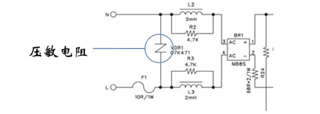
â– When the high-power equipment is disconnected or connected to the grid, the grid voltage will rise or fall. To protect the power supply, a varistor is sometimes used at the input.
â–¶ The structure of the varistor is related to its voltage. When the voltage becomes higher, the resistance decreases.
â–¶Why the varistors cannot contain impulses such as those caused by lightning strikes, since these surges may appear on the L and N lines at the same time.
Efficiency and standby power consumption 
Efficiency and standby power consumption
â– These two concepts are very simple, but there is one point to be clarified when the power supply is working:
â– Although the standby power consumption is the total loss of the power supply itself, the power consumption of the power supply itself is greater than the standby power consumption when the power supply is loaded.
â–¶ The power consumption of the power supply itself mainly comes from the loss of the inductor/transformer, the loss of the switch tube, and the loss of the diode. These losses are all related to the switching frequency. However, the current switching power supply will reduce the frequency when the output power is low. Energy-saving, so the power consumption of the power supply itself is completely different when working with a load and when it is in standby.
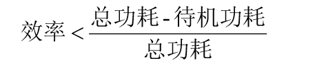
â–¶However, the efficiency is increased with the increase of load consumption. It is well understood that the efficiency in standby is 0. With the load, the power consumption of the power supply itself cannot keep up with the increase in load consumption.
ESR 
Capacitance ESR
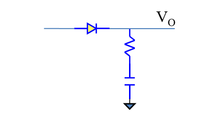
â– The switching power supply needs to add a capacitor at the output to smooth the intermittent energy delivered by the switching circuit into a stable linear output. The importance of this capacitor is self-evident.
â– A non-ideal factor is that all capacitors have equivalent series resistance (ESR), which can cause a series of problems.
â–¶ The principle of capacitance regulation is to sink current when the VO voltage rises and store energy in the capacitor. When the VO voltage drops, it discharges current and releases energy. In this process, the current always flows through the ESR.
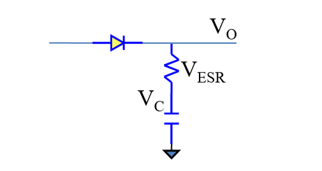
Ripple caused by ESR
â– ESR is the culprit for outputting high-frequency voltage ripple. When the capacitor stores and releases energy, the current direction is opposite, so the output is switched between VO=VC+VESR, and VO=VC+VESR. The larger the ESR, the pattern The greater the wave voltage.
Electrolytic capacitor ESR hazards
â– To reduce the cost, the output capacitor usually uses an offset electrolytic capacitor, but the ESR of the electrolytic capacitor is high.
â–¶ESR size: electrolytic capacitor> tantalum capacitor> ceramic capacitor.
â– For electrolytic capacitors, the high ripple voltage falls second, and it is fatal that the ESR will cause the capacitor to heat up. The higher the current, the more severe the heat generation, the more severe the heat, and the faster the electrolyte of the electrolytic capacitor will evaporate. Evaporation, ESR increase, fever is higher, and it is in a vicious circle.
â–¶Electrolytic capacitors themselves have low life expectancy and are the shortest device in the power system. Because of the heat generated by ESR, they will accelerate the disposal of electrolytic capacitors. Therefore, the ripple voltage of switching power supplies will increase with time.
Solve the problem of ESR
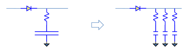
â– The solution is to reduce the ESR resistance or to reduce the current flowing through the ESR. It is difficult to reduce the current flowing through the ESR. A simpler method is to reduce the ESR resistance.
â–¶ You can use low ESR electrolytic capacitors instead of ordinary capacitors, or use multiple capacitors in parallel instead of a single capacitor.
â–¶ The disadvantage of the parallel connection of multiple capacitors is that they take up a lot of space, and their use is limited in small-sized power supplies. Therefore, ceramics and electrolytic capacitors are sometimes used in parallel, and even a multilayer ceramic capacitor replaces multiple ceramic capacitors.
dynamic 
Dynamic Response
â– Normally, the dynamic response refers specifically to the input of the power supply, and the output caused by the step change of the load is normalized after being disturbed.
â–¶ The input of AC power is continuous communication, and generally does not care about the step change of the input. The dynamic response is usually limited to describe the response when the load changes within a certain range.
â– Normally define no load as 0%, full load as 100%, and then use the load to switch between 2 percentages to define the load change.
â–¶ Commonly used load changes are 0-100, 10-90, 20-80, 25-75, depending on the application. For chargers that require hot swapping, the largest change is 0-100.
Dynamic response indicator
â– The dynamic response generally has two indicators, one is the overshoot amplitude and the other is the settling time.
â–¶ Overshoot amplitude is defined as the amplitude of the output deviating from the stable value with overshoot and undershoot.
â–¶ The settling time is the actual change from the start of the load to the acceptable output.

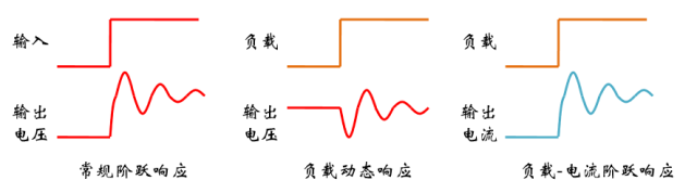
Dynamic response and step response
â– Step response refers to the input step, the output follows the step, that is to say the output should be changed to the target value as soon as possible, and the dynamic response refers to the load step, the output should stabilize as soon as possible. The two are different in form, but the essence is the same.
â–¶Using constant voltage output as an example, when the load suddenly changes, in order to maintain a constant voltage, it is necessary to adjust the current, the current adjustment process, through the load will show a voltage fluctuation, so the dynamic response of the load, its essence is the load - output The step response of the current transfer function.
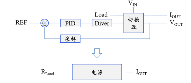
Dynamic response system block diagram
â– Consider Load as input and IOUT and VOUT as output.
â–¶ After Load is considered as input, REF is a fixed value and the transfer function of the entire system becomes the transfer function of Load-IOUT.
â–¶ For non-resistive applications such as batteries, it is also modeled as a resistor.
â– The system block diagram for adapting the general power system to dynamic response is redrawn as follows:
Thunderbolt 3 Cable
Shenzhen GuanChen Electronics Co., Ltd. , https://www.gcneotech.com