Commonly isolated and non-isolated topologies for LED general-purpose lighting applications powered by AC-DC power. The so-called "isolation" refers to the electrical isolation between the input and output using a transformer or the like. Both of these topologies have their own characteristics. In comparison, the advantages of non-isolated topologies include smaller magnetic components, higher energy efficiency, fewer component counts, lower total bill of materials costs, and mechanical design to meet safety regulations. ON Semiconductor offers a variety of non-isolated high power factor LED driver solutions that provide higher energy efficiency and compact design for different low and medium power LED general lighting applications such as linear fluorescent replacement and high power downlights and spotlights. .
Common buck non-isolated application application LED driver solution
In applications such as MR16 bulbs, 12 V landscape lighting, solar-powered LED lighting and billboard text circuits and logo backlights, the flexible step-down driver NCL30160 can be used. This device is an energy-efficient, peak-current-controlled buck controller for single-voltage inputs, providing an excellent solution for space-constrained and energy-efficient applications such as MR16 LED bulbs. But strictly speaking, the NCL30160 is a DC-DC non-buck isolation driver solution.
ON Semiconductor's NCP1015 self-powered monolithic switch control ICs are available for 1 to 8 W low power LED lighting applications such as G13, GU10, PAR16, PAR20 and recessed lights. The device integrates a 700V high-voltage MOSFET in a PDIP-7 or SOT-223 package to provide all the features needed to build a robust, low-cost AC-DC LED power conversion solution. This device can be used in both isolated and non-isolated solutions to meet different application requirements. Among them, the NCP1015-based non-isolation scheme uses a tapped inductor to isolate the AC signal, improve the duty cycle of the MOSFET, improve system energy efficiency and circuit performance, and achieve a power factor greater than 0.7 by reducing the capacitance or valley fill circuit.
In lighting applications, LED drivers face power factor correction (PFC) problems if the output power requirement is above 25 W. For example, in the solid-state lighting standard of the US “Energy Star†project, there is a mandatory requirement for PFC (regardless of the power level), that is, the power factor is higher than 0.7 for residential applications, and the power factor is high for commercial applications. At 0.9. In this type of application, ON Semiconductor's NCP1607 Critical Conduction Mode (CrM) scheme can be used for both isolated and non-isolated solutions.
High power factor non-isolated LED scheme supporting dimming
Some AC-DC non-isolated LED lighting applications require both high power factor and support for dimming, such as analog, digital (PWM) or triac dimming (TRIAC) dimming. In these applications, customers can use ON Semiconductor's NCL30000 power factor correction TRIAC dimmable LED driver or LV5026/29 series high power factor dimmable LED driver.
I. NCL30000/2 non-isolated dimmable high power factor LED driver topology and application
The NCL30000 is a power factor correction dimmable LED driver for LED lighting applications such as residential and commercial lighting. The NCL30000/2 is available in a compact 8-pin surface mount package that uses a critical conduction mode (CrM) flyback architecture to provide a high power factor greater than 0.95 in a single-segment topology, eliminating DC-DC Conversion segment. Typical applications include LED driver power supplies, LED downlights, triac TRIAC dimmable LEDs, and power factor corrected constant voltage power supplies. This device is compatible with leading edge TRIAC dimmers and trailing edge transistor dimmers. Depending on the dimmer used, the LED output can be adjusted down to 2%.
The NCL30000 operates with a constant on-time CrM and is ideal for isolated flyback applications, but can also be configured as a non-isolated high power factor topology. In the non-isolated topology, the NCL30002 has higher current accuracy (±3.1%) at operating temperatures from -40 to 125°C, including different options for buck and buck-boost topologies, as described below. Comparison.
1) NCL30000 non-isolated buck and buck-boost topology comparison
In terms of topology, the disadvantage of the buck topology is that the input current waveform is dependent on the output voltage. In this configuration, since the inductor and the LED string are arranged in series, current flows only when the input voltage exceeds the forward voltage drop (VF) of the LED; CrM and constant on-time operation provide high power factor; direct sensing LED current; low loop bandwidth supports high power factor operation; MOSFET current is equal to LED peak current; MOSFET voltage stress is equal to peak mains voltage; power factor (PF) and total harmonic distortion (THD%) performance depends on output voltage drop and The ratio of input voltage (VF/Vin), the higher the ratio, the lower the PF; the higher the ratio, the higher the THD.
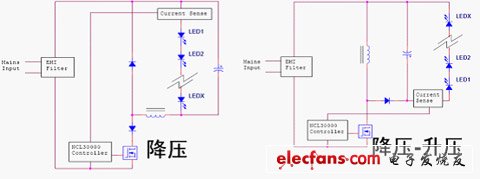
Figure 1: Comparison of Buck and Buck-Boost Configurations
In comparison, the input current waveform of the buck-boost topology is load-independent, with high power factor and good total harmonic distortion performance. In the buck-boost configuration, the inductor is not connected in series with the LED string. The input current waveform or distortion is independent of the output voltage drop (VF). The inherent LED fault protection provides protection when the MOSFET is shorted; the LED forward voltage drop can be Above or below the input voltage; the MOSFET switching voltage stress is the sum of the input voltage and the output voltage drop (Vin+Vout).
30-50W Solar Street Lights,30W Solar Street Light,45W Solar Street Light,50W Solar Street Light
Yangzhou Bright Solar Solutions Co., Ltd. , https://www.solarlights.pl