There is a well-known saying in the Hi-Fi world that is "briefness first." That is to say, if a circuit can be made with one component or device, it is not necessary to use two. Electronic components commonly used in electronic circuits are resistors, capacitors, inductors, etc., and commonly used electronic devices are diodes, transistors and integrated circuits. Resistors and capacitors are all linear components, which can be considered as non-linear distortion caused by them in the amplifier circuit. However, the electronic devices currently used for amplification, whether they are tubes, transistors, or integrated circuits, are all non-linear devices, which are the source of non-linear distortion in the amplifier circuit. Therefore, as few tubes as possible should be used in the amplifier circuit. It is not easy to do this, so the amplifier circuits usually seen are more complicated. To be "concise", two problems must be solved: one is that the magnification should be large enough, at least it should be able to reach the rated output power when connected to the CD player; second, the nonlinear distortion should be as small as possible, without negative feedback or When a small amount of negative feedback is added, the harmonic distortion coefficient can meet Hi-Fi requirements.
The output circuit of the power amplifier can be divided into two types according to the presence or absence of output transformers. The power amplifier circuit without an output transformer must use capacitive coupling (OTL circuit) or two sets of positive and negative power supplies (OCL circuit) in order to make no DC current flow through the speaker. The transistor Class A audio amplifier introduced in this article uses a single-tube amplification method with a transformer output. Only two tubes are used for each channel. If complementary push-pull circuits are used, at least four or five tubes are required. Since the primary impedance of the output transformer used is only a few tens of ohms, it is easy to wind and the performance can easily meet the requirements. One of the outstanding advantages of using transformer output is to avoid burning speakers. In addition, the extremely small DC resistance of the transformer secondary winding will improve the damping of the speaker and reduce transient distortion.
Circuit structure and characteristics
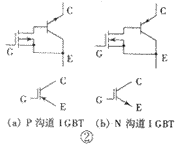
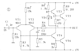
The transistor Class A audio power amplifier circuit and power supply circuit are shown in Figure 1. This power amplifier circuit has an effective value output power of up to 15W. It uses only two transistors and directly connects them to form a high transconductance power field effect transistor. This is the author's occasional thought inspired by insulated gate bipolar transistors (IGBTs). IGBT is a new type of semiconductor power device, which has been successfully used in high-frequency switching power supplies. In recent years, it has also been seen in high-fidelity audio power amplifiers. It has both the advantages of bipolar transistors (that is, ordinary PNP, NPN transistors) and unipolar transistors (that is, field effect transistors), but does not have their own shortcomings, so the application prospect is very broad. The saturation voltage drop of ordinary transistors is small, but the switching speed is slow, and it is a positive temperature coefficient. The field effect transistor does not require input current, the switching speed is fast, it has a negative temperature coefficient, but the on-resistance is large. The equivalent circuit of the IGBT is shown in Figure 2. In the figure, (a) shows the IGBT equivalent circuit composed of a P-channel field effect transistor and an NPN transistor, and (b) shows an N-channel field effect transistor. Equivalent circuit of IGBT combined with PNP transistor. Since the main design purpose of the current IGBT is for a switching circuit rather than a linear amplifying circuit, the linearity of its output characteristic curve is not very good. The author uses a high-performance Hitachi famous tube 2SJ77 and a domestic high-power transistor 3DD9 to form an output tube according to the IGBT structure. 2SJ77 (the complementary tube is 2SK214) is a medium power MOSFET specially designed for linear amplification. It is often used as a driving tube in high-fidelity power amplifiers and has a good reputation. Its transconductance is up to 40mA / V (or 40mS), and the input capacitance CIS is 90pF, which is less than one-sixth of the input capacitance of the high-power FET 2SJ49 (2SK134).
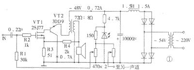
This composite method has the following significant advantages: (1) It has extremely high transconductance and can produce sufficient voltage gain. The transconductance of 2SJ77 is 40mA / V. Because the drain of VT1 is directly connected to the base of VT2, the emitter current of VT2 is (β + 1) times the drain current of VT1. If the current amplification factor β of VT2 is 50, the transconductance of this composite pipe is 2000mS. That is to say, the transconductance of the field effect tube VT1 is enlarged by about β times by VT2. In the circuit shown in Fig. 1, β of 3DD9 is selected as 40. When R3 is shorted and R4 is open, the open-loop voltage magnification is 60. The maximum output power is 15W when the load is 8Ω, and the effective value of the required input voltage can be calculated to be about 0.18V. When R3 = 51Ω, the voltage amplification when R4 is open is about 30, which means that R3 produces negative feedback of -6dB. When R3 = 51Ω, R4 = 2kΩ, the total voltage magnification is 15, and the total negative feedback is -12dB. The feedback generated by R3 is current series negative feedback, and the feedback generated by R4 is voltage series negative feedback, each at -6dB. (2) VT1 is a current drive for VT2, and the base current of VT2 is the drain current of VT1, so odd harmonic distortion generated by bipolar transistor VT2 can be avoided. The gate-source voltage UGS of the field effect tube and the drain current ID have a square relationship. Although not a linear relationship, in theory, only the second harmonic distortion will occur. The base-emitter voltage UBE of the bipolar transistor and its collector current IC have an exponential relationship. If a voltage source is used for excitation, both odd and even harmonic distortions will be generated. However, if current driving is used, the collector current IC has nothing to do with the base emission voltage UBE, and the generation of odd harmonic distortion can be avoided. The sound of this power amplifier is mellow and warm, and it has the taste of a tube amplifier. The reason may be this. (3) The collector of the output tube VT2 of the composite tube is directly grounded, so there is no need to add an insulation pad to the radiator, which is helpful to reduce the thermal resistance, which is more necessary for the Class A power amplifier that generates more heat. In actual installation, 2SJ77 should be close to 3DD9, the purpose is to generate thermal coupling, and use the negative temperature coefficient of the MOS field effect tube to improve the temperature characteristics of the entire amplifier circuit. If no negative feedback is added, the 2SJ77 can also not be added with an insulation pad, because its source (that is, the middle pin) happens to be the case. (4) This composite tube has better linearity than the current IGBT tube, and the price is low.
The bias circuit of the power amplifier circuit uses light-emitting diodes as the bias voltage to stabilize, and can keep the quiescent current basically unchanged when the power supply voltage fluctuates.
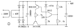
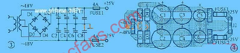
The power circuit uses a choke coil input inverted L-type filter circuit, and the output DC voltage is about 0.9 times the effective value of the secondary voltage of the power converter. The filter inductor requires an inductance greater than 1H and a current greater than 1.5A. If you feel that the choke is not easy to make and install, you can also use the regulated power supply shown in Figure 3. Because the single-ended amplifier circuit does not suppress the power supply ripple, if you do not use a choke or a regulated power supply and only rely on capacitor filtering, there will still be tens of millivolts of hum even when the capacitor is used to 20000μF.
VT1 and VT2 in the circuit shown in Figure 1, if you use MJ29585 and 2SK214, the output power is 10W. It should be noted that the composite tube belongs to the N-channel IGBT, so the polarities of the components and components in the power supply and circuit must be reversed.
Installation, commissioning and technical indicators
1. Selection of components The output tube VT2 uses domestically produced 3DD9 (F-3 metal package), and high power tubes such as 2SC2922 can also be used, but the left and right channels are required to have the same characteristics. It is best to use a transistor characteristic chart tester to select a tube with good linearity (that is, the curve is evenly spaced), but it should be noted that the test conditions should be as close as possible to the actual working state. The authentic inlet pipe has better linearity and better consistency. The dispersion of domestic pipes is relatively large, so you need to be patient. Special attention should also be paid to the maximum reverse breakdown voltage between the collector and the emitter of the transistor when the base is open. This voltage should be more than three times the power supply voltage (that is, not less than 160V), and a certain margin should be left. Otherwise, when the speaker is open, the induced voltage generated by the output transformer will easily break the tube.
When the current amplification factor of VT2 is 40 and the quiescent current of the collector is 0.7A, the base current is about 17.5mA, which is equal to the drain current of VT1. In order to make the static working current of VT1 not too small and enter the nonlinear region, the current amplification factor of VT2 cannot be too large. For example, if the current amplification factor of VT2 is selected to be 100, the drain current of VT1 is only 7mA, which can make the collector current of VT2 reach 0.7A. The β value of common imported high-power tubes (such as Sanken's 2SC2922, Toshiba's 2SC3281, etc.) is generally above 90, so VT2 uses domestically produced 3DD9. The domestically produced 3DF10C uses F-4 type metal package, which is also very good.
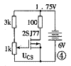
Push tube VT1 selects 2SJ77, also need to select and match under the conditions close to the actual working state. The selection and pairing of 2SJ77 can be carried out using the circuit shown in Figure 4. , 6V power supply can use 4 No. 1 dry batteries. Adjust the 1kΩ potentiometer to make the voltage on the 100Ω resistor to 1.75V, then the drain current is 17.5mA. Then use a digital multimeter to measure and record the DC voltage UGS of the grid to the source at this time, and select two tubes with similar UGS. If you want to measure 2SK214, don't forget to reverse the polarity of the power supply. MOS type field effect tube is more delicate, so when using the transistor characteristic chart tester, special care should be taken to prevent the tube from being damaged due to poor grounding.
The power capacity of the power transformer should not be less than 150VA, and the secondary rated current should not be less than 2A.
The manufacturing process of the output transformer is much simpler than that of the amplifier. The primary impedance is required to be 72Ω. If the secondary load impedance is 8Ω, the primary to secondary turns ratio is 3: 1. The output transformer used for this power amplifier is customized at Dingzhou Feida Electronics Factory, or you can make your own by referring to relevant materials.
The adjustment tube in the regulated power supply adopts the domestic germanium transistor 3AD30C, which requires its current amplification factor to be not less than 70. Although the voltage stabilizing circuit is a collector output circuit, since the penetration current of the germanium tube is relatively large, it is not necessary to additionally provide a startup circuit. The collector of the adjusting tube can also be directly grounded. The voltage regulator diode uses μ574, which is an integrated circuit specially used for stabilizing the tuning voltage of the high frequency head in the color TV, and the effect is very good. At the same time, the sampling resistance should be adjusted so that the output voltage is + 38V, and the secondary voltage of the power transformer should also be reduced to about 43V.
2. Installation and commissioning The output tube VT2 will generate a large amount of heat when it is working, so a radiator with a sufficient area should be added, and the surface of the two should be coated with thermal grease. Because the amplifier circuit is very simple, it is soldered in a scaffolding way, and it is enough to find three terminal frames with 4 solder tabs. Install the two tubes of each channel on the same radiator, as close as possible. The lead wire near the gate end of the anti-self-excited resistor R2 (1kΩ) should be as short as possible. In order to ensure that the MOS field effect tube will not be damaged during welding, the three electrodes of the MOS field effect tube can be wound together with a thin fuse, and then disassembled after the entire circuit is welded. Despite this, it is important to pay attention to whether the metal shell of the soldering iron is well grounded. The safest method is to unplug the power plug of the electric iron and use the residual heat for welding.
The adjustment of the whole machine is very simple, as long as a 1A DC ammeter is connected in series in the primary loop of the output transformer, and then the corresponding adjustable resistance is adjusted so that the total current of the two tubes is about 720mA. You can also connect a 0.1 to 0.3 ohm sampling resistor, measure the voltage at both ends and then convert the current value.
3. The main technical indicators The main technical indicators of the audio power amplifier are as follows: frequency response is 25Hz ~ 45kHz (-1dB), 12Hz ~ 66kHz (-3dB); maximum output power is 15W (RMS); sensitivity is 0.73V (RMS) ; Residual noise (when a stable power supply is used) is 0.32mV; the highest efficiency (sine wave) is 43%.

Follow WeChat

Download Audiophile APP

Follow the audiophile class
related suggestion
Avago Introduces New High Linear Power Amplifier Module Product Avago Technologies ...
The circuit is shown in Figure 1. The chip IC uses the LM1875 of the American NS company, which has a soft tone and low distortion (0.015% ...
The word "Monster" has both positive meaning and ...
When the output power of the digital power amplifier is greater than 50W, it is impossible to use only ...
If an "audiophile" is a group of people who are never satisfied with the sound and "loved the new and the old" with the audio equipment. Then just rely on these so-called "fever spirits" ...
First, the circuit principle and characteristics 1. Power amplifier part (see Figure 1)
Simple and practical TDA2822M integrated power
TDA2030 is ...

STK465 thick film ...

This RF power amplifier can output 2-3 channel signals, covering an area of ​​about one square kilometer, is ...
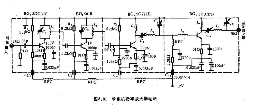
![[Photo] 15w RF power amplifier](http://i.bosscdn.com/blog/20/06/41/521040781.gif)
![[Photo] Broadband high frequency power amplifier](http://i.bosscdn.com/blog/20/06/41/520536801.jpg)
Low frequency power amplifier
![[Photo] TDA2030 audio power amplifier](http://i.bosscdn.com/blog/20/06/41/5131012891.gif)
Looking at the Hi-Fi amplifiers currently on the market, the output power is 100W ...
![[Photo] Transistor 15W Class A Power Amplifier](http://i.bosscdn.com/blog/20/06/41/513102891.gif)
With the newly launched LM4651 and LM465 from National Semiconductor ...
![[Photo] 125W Class D Subwoofer Power Amplifier](http://i.bosscdn.com/blog/20/06/41/513100868.jpg)
![[Photo] Mark Levinson No. 30 ...](http://i.bosscdn.com/blog/20/06/41/513544752.jpg)
EL34 (6CA7) was first launched by Philips in 1956 ...
![[Photo] 45W transistor tube hybrid power amplifier](http://i.bosscdn.com/blog/20/06/41/513531952.jpg)
This article cleverly combines the electronic tube EL34 and the transistor (op amp), ...
![[Photo] 32W hybrid audio power amplifier](http://i.bosscdn.com/blog/20/06/41/513526493.jpg)
The pre-amplifier adopts a European-made TESLA brand low noise high cheek double transistor ...
![[Photo] Gallstone hybrid power amplifier using switching power supply](http://i.bosscdn.com/blog/20/06/41/513524776.gif)
"Simple" means the circuit of the amplifier is simple, making it easier, as long as the picture ...
![[Photo] Simple fool power amplifier](http://i.bosscdn.com/blog/20/06/41/513432946.jpg)
1. Description: & nb ...
![[Photo] LM386 low voltage audio power amplifier ...](http://i.bosscdn.com/blog/20/06/41/513417261.gif)
The Class A transistor power amplifier has a warm and sweet tone, which makes people tempted. But the temperature rise of Class A amplifier ...
![[Photo] Class A power amplifier using SAP15N / P audio pair tube ...](http://i.bosscdn.com/blog/20/06/41/513346769.gif)
The circuit is shown in Figure 5, ...
![[Photo] Using TDA7294 and 2SA1216 / 2S ...](http://i.bosscdn.com/blog/20/06/41/4233420295.gif)
'+ data.data.username +' '; dom + ='
â—High-efficiency, energy-saving design, full display of green concept from inside to outside
The system adopts a high-efficiency rectifier, the peak efficiency of the rectifier is greater than 96.2%, and the power consumption of the rectifier sleep is as low as 4W or less.
â—The rectifier module is small in size and high in power density, improving the utilization of cabinet space
â—Fully digital design, more stable performance
The rectifier adopts DSP+MCU dual digital circuit control mode, the system adopts CAN+RS485 dual bus control, the system power supply reliability is higher, and the transmission rate is faster.
High efficiency rectifier
Changzhou Changyuan Electronic Co., Ltd. , https://www.cydiode.com