0 Introduction With the progress of urbanization and the popularity of automobiles, traffic congestion has intensified, traffic accidents have occurred frequently, and the traffic environment has deteriorated. This has become a serious problem that has long plagued developing countries and developed countries. The direct way to solve this problem is to improve the capacity of the road network. There is limited space for roads to be built, and construction funds are difficult to raise. The transportation system is a complex and large system. From the perspective of system theory, we should consider the combination of vehicles and roads, use various high-tech systems to solve traffic problems, and the intelligent transportation system emerges as the times require.
This article refers to the address: http://
The entire intelligent transportation system is centered on the positioning and navigation of the vehicle. The vehicle navigation system is the central component of the intelligent transportation system and is the basis of other various functional applications. GPS or GPS/INS or GPS/DR solutions are widely used in vehicle navigation systems due to their simple structure, low cost, high precision and good dynamic performance. This paper is to achieve combined positioning, using map matching (MM) positioning technology for vehicle positioning, in order to provide users with accurate and reliable real-time positioning information during driving, providing technical support for the realization of intelligent traffic management system.
1 map matching principle
Map matching is a software-based positioning correction method. The basic idea is to associate the vehicle positioning trajectory with the road network information in the digital map, and thereby determine the position of the vehicle relative to the map.
The map matching application is based on the following two assumptions:
(1) The vehicle is always on the road;
(2) The accuracy of the adopted road data is higher than the positioning accuracy of the vehicle positioning navigation system. When the above conditions are satisfied, the positioning data and the vehicle running trajectory can be compared with the road position information provided by the digitized map, and the most suitable driving section of the vehicle and the maximum possible position of the vehicle in the road section are determined through an appropriate matching process. . If the above assumptions are not true, the map match will result in an incorrect location output and may result in a severe degradation in system performance. It is generally believed that the digital map error used for matching should not exceed Qiaomi (true ground distance). Since the land vehicle is located in the road network most of the time except for entering the parking lot, the conditions for using the map matching technique are satisfied.
2 map matching algorithm
The map matching algorithm is a fusion of the curve matching principle and the geospatial proximity analysis method. The basic idea of ​​the curve matching algorithm is: If any curve is divided into any number and any proportion, and the segmentation points fall on the other curve, the two curves are strictly matched. In practical applications, the average value of the distance from a certain number of division points on a curve to the reference curve is calculated as the average distance to the reference curve, and the reciprocal of the average distance is used as a measure of the matching pros and cons. The spatial proximity analysis method is to match the current positioning data according to the closest method in space in the known possible correct geographic data set.
The map matching algorithm can be divided into two relatively independent processes: one is to find the road on which the vehicle is currently traveling; the other is to project the current positioning point onto the road on which the vehicle is traveling. The basic method is to search all road segments and their combinations in the vicinity of the vehicle track according to the idea of ​​curve matching, and find the matching metrics between the combined routes and the vehicle track respectively, and obtain the combined route of the best matching metrics. As the current driving route of the vehicle. The commonly used algorithms for map matching are as follows: direct projection algorithm; correlation algorithm; semi-deterministic algorithm; probability statistical algorithm; fuzzy logic algorithm; based on computational geometry (non-numeric calculation) knowledge (and temporarily does not consider measurement error) algorithm.
Since the computational geometry knowledge algorithm does not require data fusion, it is rarely necessary to consider the driving direction, which is very intuitive and reduces many numerical calculations. It has a very high correct matching rate and can meet the requirements of quickly, accurately and real-time positioning of the vehicle position. Therefore, the system uses a map matching algorithm based on computational geometry knowledge.
Based on computational geometry (non-numeric calculations) knowledge (and temporarily do not consider measurement errors), there are two ideas based on the measurement point coordinates:
(1) It is continuously judged which side of the road the newly measured point is located, and if the point just measured and the point measured in the previous stage are located on both sides of the road 1, the vehicle travels on the road 1. If the road 1 is a curved path, then the method can be used to determine the road on which the vehicle is located after multiple measurements.
(2) Calculate the convex hull of the measurement point set piece by piece, and judge which road the vehicle is driving according to the intersection of the road and the convex hull.
But when the measurement points are all on the same side of 1, the algorithm fails. In addition, the algorithm does not consider the measurement error, and thus the poor noise immunity of the GPS measurement error is likely to cause the algorithm to fail.
3 improved map matching method
In the design of the algorithm, it is based on the following four aspects: First, the efficiency, the map matching algorithm must be able to meet the real-time and fast requirements of vehicle navigation; second, the accuracy, the purpose of map matching is to effectively improve the accuracy of the vehicle positioning target, and to maintain The stability of the positioning results; third, different traffic conditions give strategic treatment to improve the accuracy of road selection and shorten the matching time; Fourth, program design, must be quantified to ensure the possibility of programming. Based on the above considerations, the following map matching algorithm is proposed, and the algorithm is divided into three steps.
3.1 Data preprocessing process
The knowledge base formed by various rules filters out the abnormal positioning data and effectively interpolates it. The main considerations are: the PDOP value provided by the GPS board (generally taking PROP>6), the map range (predetermined effective geographical area of ​​the vehicle), and the speed of the vehicle. The rules are as follows:
Rule 1 IF PDOP>6 THEN GPS data is abnormal, transfer rule 5;
Rule 2 IF Pos (L, B) NOT IN MapArea THENGPS data is abnormal, transfer rule 5;
Rule 3 IF Pos(V)>Const Car Speed ​​THENGPS data is abnormal, transfer rule 5;
Rule 4 IF Pos(V) Rule 5 The IF Car In tunnel or overpass THEN GPS data is abnormal; the ELSE DR subsystem initiates acquisition of positioning data.
Among them, MapArea is the pre-set geographical range theoretical range of vehicle travel; Pos(L, B) is the current vehicle GPS positioning data; Pos(V) is the current vehicle travel speed; Car Speed ​​is the preset maximum vehicle travel speed. Theoretical value.
3.2 Determination of the road segment of the vehicle
After the United States cancels the SA intervention policy, the accuracy of the GPS is less than 25 m under normal conditions, and most of the road sections can be directly projected to obtain the road of the current vehicle. The situation that is difficult to judge generally occurs when the GPS positioning accuracy is lowered due to poor vehicle visibility conditions or when the vehicle is at a road intersection.
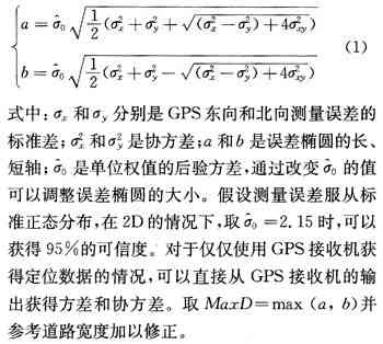
Let ΔCdistance be the distance between the GPS value and the current road projection point; Δdistance is the distance between the GPS value and other road projection points; MaxD is the distance threshold of the preset search road. The threshold is usually determined according to a probability criterion, ie the actual position of the vehicle must be included with a certain probability. According to statistical theory, an error ellipse can be determined first:
The rules for determining the road segment of a vehicle are as follows:
Rule 1 When the calibration information of the electronic map is received, such as a route planned driving route or a user-defined road attribute type code, the calibration information is directly used to match the planned road segment;
Rule 2 The number of roads searched by IF within a certain threshold <1THEN vehicle is not on the road. Using the probability and statistics algorithm, a dynamically adjustable point buffer can be used to replace the error ellipse according to the GPS real-time positioning data, and the error ellipse expansion factor is utilized. The principle is to set the buffer expansion scale factor, and the dynamically adjustable buffer radius is searched for the road segments that fall into the buffer from small to large in the order of 30 m, 60 m, 90 m and 120 m. In the case of GPS positioning failure, the error parameters of the DR (dead reckoning) positioning must be used instead of the GPS parameters to complete the definition of the error region to ensure the continuity of the matching process. At this point, it should be noted that due to the error accumulation effect of DR estimation, statistical model errors, measurement errors and various random errors will continue to accumulate as the estimation process proceeds. Therefore, after defining the error ellipse according to the error parameter of DR positioning, the appropriate expansion factor should be multiplied to expand the error area to reflect the influence of error accumulation on the positioning accuracy. The cutting algorithm is used to quickly determine the candidate road segment. The calculation can not only determine the road segment falling into the buffer zone, but also obtain the intersection point of the road segment and the buffer zone, thereby obtaining the coordinates of the matching point of the GPS positioning data;
Rule 3 The number of roads IF searched within a certain threshold = 1THEN uses the direct projection algorithm to use this road as the current road on which the vehicle travels;
Rule 4 Number of roads searched within a certain threshold>1&&The same road node number THEN vehicles travel at road intersections, according to traffic conditions, A, B, C, D, take corresponding strategies, and use correlation algorithms, Calculating the correlation coefficient between the measured trajectory and the 1 set of map data, and the route with the highest correlation with the actual measured route among all the candidate map routes is the real route of the vehicle traveling;
Rule 5 The number of roads searched within a certain threshold>1&& different road node numbers THEN vehicles travel between parallel roads with close distances, using the linear combination method of distance and direction elements in the fuzzy logic algorithm to improve the algorithm, Let p1+p2=1, and determine the value of the fuzzy decision rule of the weighting factor Q of the similarity measure function in the p2 reference fuzzy logic algorithm mode, and then calculate the similarity measure function s of the map matching algorithm based on curve fitting And select the minimum value as the road segment to be matched, that is, the road segment is optimal when considering the angle and distance factors.
The weighting factor q takes the following values:
Rule 5.1 IF roads are prohibited or prohibited from turning or one-way reverse THEN q="1".5*q;
Rule 5.2 IF existing path planning and path planning road section THEN q="0".5*q;
Rule 5.3 The IF road is in line with the direction of travel of the vehicle, THEN q="0".25*q.
Rule 6 IF finds that if the road is demarcated, the lower-level road description is not detailed enough, the vehicle enters the parking lot, etc., and the matching road segment can not be found. The manual stop map matching is performed, and the original data received is directly displayed. Perform error correction.
3.3 Fuzzy logic based matching road segment credibility evaluation
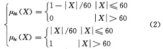
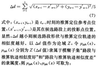
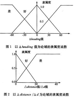
The difference between the candidate segment orientation and the vehicle traveling direction (Δheading, unit: degree) is the domain X, and the value x of μhh(X) and μhc(x) is the orientation difference (unit: degree) belongs to the fuzzy subset. The degree of membership of "the road section is consistent with the vehicle's driving orientation" and "the road section is inconsistent with the vehicle's driving orientation", then μhh(X) and μhc(X) can be taken as:
At the initial position given, the DR estimator can accurately describe the trajectory of the vehicle in a short time. Therefore, the similarity between the candidate road segment shape and the current vehicle travel trajectory can be defined as follows: According to the DR estimation principle, the vehicle position (xn, yn) at the current time tn and the vehicle travel orientation θn can be based on the vehicle at the previous time tn-1. The position (xn-1, yn-1) and the driving orientation θn-1 are derived by the following formula:
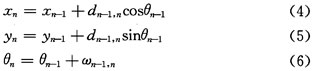
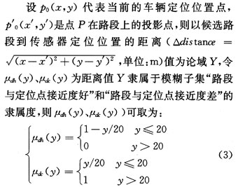
Where: dn-1,n is the distance traveled by the vehicle from tn-1 to tn, ωn-1,n is the amount of change in the vehicle's driving orientation from time tn-1 to tn (dn-1, n and ωn-1, n are provided by the vehicle displacement sensor and the angular velocity sensor). Taking the projection point p'0(x', y') of the current positioning position p0(x, y) of the vehicle on the candidate road segment as the reference position for estimating the positioning at the time tn, taking the reference driving orientation of the candidate road segment at the time tn, Then, the DR calculation formula can deduct the estimated positioning reference point at the previous moment. A set of reference points can be obtained by multiple calculations, and the specific quantity can be determined according to the requirements of the actual application. Here, the number of reference points is 5, and the average distance difference (unit: m) of the DR positioning trajectory between the candidate road segment and the first 5 unit time can be defined as:
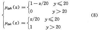
The graph of the above membership function is shown in Figures 1 and 2.
Based on the above membership function, it is possible to make a comprehensive evaluation of the possibility that the candidate road segment is the road segment where the current vehicle is located. Taking this possibility as the domain U, the Cartesian product set of its element u and the domain X, Y and Z:
![]()
Its elements (x, y, z) correspond, that is, u is related to three factors. Therefore, in the fuzzy evaluation of u, the factor set can be taken as E={X, Y, Z), the comment set can be taken as F={large, small), and the comprehensive evaluation is performed as follows:
(1) A single factor evaluation of u, and then using the results to construct a fuzzy matrix representing the fuzzy relationship between E and F. Let the single factor evaluation results of the factors X, Y, and Z be the fuzzy vector R1=[μhh(x), μhc(x)], R2=[μdh(y), μdc(y)] and R3=[μ△, respectively. Dh(z), μΔdc(z)], the above fuzzy vectors are combined to obtain a fuzzy matrix representing the fuzzy relationship between E and F.
![]()
(2) Determine the weight vector P = [p1, p2, p3], where p1, p2, p3 respectively indicate the importance of the factors x, y, z in the chaos, p1 + p2 + p3 = 1.
(3) For the fuzzy transformation Q=P°R, the obtained fuzzy vector Q is the evaluation result of the evaluated object U on the comment set F, and the two components indicate the extent to which the candidate road segment is the possibility of the road segment where the vehicle is located.
In the above comprehensive evaluation algorithm, the fuzzy matrix multiplication "°" uses a simple weighted average type operator (⊕, ×) in order to balance the various factors. Since the sum of the components of the weight vector is 1, the operation ⊕ degenerates into a general real addition, so the operator (⊕, ×) can also be rewritten as (+, ×). In this case, the multiplication of the fuzzy matrix is ​​exactly the same as the multiplication of the ordinary matrix.
With the evaluation of the possibility that the candidate road segment is the current vehicle traveling road segment, the reliability of the positioning result corrected by the map matching with the candidate road segment position as a reference can be evaluated. In the evaluation, the connectivity of the candidate road segment to the matching road segment should be considered. For this reason, the following rule is introduced: if the candidate road segment is the matching road segment at the previous time or is connected with the matching road segment at the previous time, the candidate road segment is utilized. Corrected the positioning results with high credibility. Taking the correction result as the evaluation object, the evaluation index matrix is ​​(Q, Q'), where Q is the probability evaluation matrix of the candidate road segment, and Q' is the connectivity evaluation matrix. When the candidate road segment has a connected relationship with the previous time matching road segment When Q' is taken as the probability evaluation matrix of the matching road segment at the previous time, otherwise it is replaced by the 0 matrix. The evaluation weight vector is P'=[p'1, p'2, p'3, p'4], the components of which correspond to the respective components of Q and Q', respectively, and p'1+p'2+p' 3+p'4=1. Multiplying the indicator matrix by the weight vector yields μ=p'°[Q,Q']T, which is the credibility of the modified positioning result, which provides a clear basis for selecting the best matching segment.
4 experimental results
The intersection is the most error-prone place in the map matching process. According to the improved map matching algorithm theory proposed in this paper, the performance analysis of the intersection problem is discussed in two cases.
The first case: the vehicle goes straight through the intersection, as shown in Figure 3.
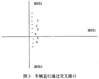
The track points 4, 5 are close to the road segment 1, but the straight line obtained by the track points 1, 2, 3, 4, 5 is far from the road segment 1, close to the road segment 2, so the track point 5 will correctly match the road segment 2, and will not be mistaken. Match the ground to the road segment 1. Similarly, track point 4 also correctly matches to segment 2. Since the continuity of the trajectory is considered, compared with the direct projection algorithm based on the position point, the algorithm of this paper is not easy to have a matching error at the intersection.
The second case: the vehicle turns through the intersection, as shown in Figure 4.
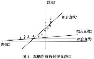
The angle between the fitted straight line 1 and the road segment 2 obtained by fitting the track points 1, 2, 3, 4, 5 is less than 30 degrees, and the point 5 is matched to the road segment 2. Similarly, the angle between the fitted straight line 2 and the road segment 2 obtained by fitting 2, 3, 4, 5, and 6 is also less than 30 degrees, and the point 6 is matched to the road segment 2. It can be seen from the figure that the angle between the fitted straight line 5 and the road segments 1 and 2 obtained by fitting points 5, 6, 7, 8, and 9 is greater than 30 degrees. It is known from the basic principle of the algorithm that 9 does not meet the matching condition. Do not match. Match the other points one by one in the same way. Although a small number of track points can not be matched near the intersection, the matched track can reflect the actual travel trajectory of the vehicle, and the map matching problem at the intersection is better handled.
In order to verify the influence of the map matching algorithm proposed in the paper on the positioning accuracy of the navigation system, the algorithm is used to test the measured data of the sports car. The matching results show that the vast majority (>96%) of the positioning data can be matched to the road relatively accurately, and the matching positioning accuracy is improved; the matching algorithm realizes real-time and can meet the actual needs (1 time/s); The system can recognize and match when the GPS is blocked to a certain extent.
3000mAh GPS Smartphone,GPS Slim Smartphone,GPS Phone
Bluetooth Headphone Co., Ltd. , http://www.nssmartphone.com