Abstract: A single-body central controller is realized by using MC9S12XS128, which realizes the control of central centralized control door lock, external light, internal light and wiper. At the same time, the anti-theft alarm function and remote door lock control are realized by RF technology. The bus implements control of four windows.
This article refers to the address: http://
Keywords: LIN; centralized control door lock; anti-theft alarm introduction
Automotive electronics has entered a large-scale application stage, and technologies such as bus technology, intelligent sensing, short-range wireless, and radio frequency communication have greatly improved the intelligence level of automobiles and expanded the use space of automobiles. According to the different fields of use, automotive electronics are generally divided into four parts: body control system, power system, driving control system and infotainment system. For the body control system, centralized control and distributed control are generally adopted. design.
For cost-sensitive low-end cars, centralized control can better control costs, and for mid- to high-end cars with certain functional upgrade requirements, distributed systems are used to facilitate the expansion and upgrade of functions. At present, automobile manufacturers generally adopt different schemes for different vehicle configuration levels. For a low-profile of a certain vehicle system, the central controller of the vehicle body is more concentrated, and for the high-distribution, some functions of the vehicle center controller are It is realized in the form of a single node, and adds some intelligent functions. The CAN bus or the LIN bus communicates between the node and the central controller of the vehicle body [1]. For example, the window lifting function in the central controller can be separated. Realize and realize intelligent window anti-pinch function in single node form.
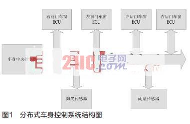
Figure 1 is a distributed body control system realized by a LIN bus design of a certain model, including a body central controller (hereinafter referred to as BCM), four window nodes and two sensor nodes, wherein the BCM acts as the LIN master node and receives the window from the window. The status signals of the nodes and sensor nodes and the control of the window nodes are the most important units of the body control system. The following combines the experience of BCM developed for this model, and details the system structure of BCM and its hardware and software implementation.
BCM system structure
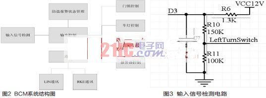
BCM is a typical control system. Its input interface includes a series of switch signals and pulse signals. The control objects include door locks, lights, wipers, windows, alarms, communication via RF signals and remote control car keys, via LIN bus and sensor nodes. And the window node communicates, and its system structure is shown in Figure 2.
As can be seen from Figure 2, the output control is the core module of BCM, and the input signal detection, communication, and burglar alarm status management are all for output control. The following describes the hardware design and software development in terms of input signal detection, output control, and LIN communication.
Input signal detection
The BCM input signal includes a switching signal and a pulse signal according to the nature of the input signal and its detection mode. In terms of electrical characteristics, these signals are represented by a single physical connection in the form of high and low levels, in which the vehicle speed signal and the collision signal are pulse signals with periodic characteristics, and the switching signals are time-discreted and externally input (generally human operation). ) Decided.
Input detection is relatively simple in hardware design, simple current limiting and filtering [2], after voltage division, it can be directly connected to the IO pin of the microcontroller, as shown in Figure 3.
In the output control logic that appears in combinatorial logic, stimulus B triggers control C if condition A is satisfied. The state of the switching signal and its changes are often used as conditions and excitations for a certain control logic. Therefore, for such a switching signal physically represented as a single connection, logically corresponding to three variables, respectively representing the switching signal Current status and changes. If the left turn signal switch corresponds to the physical signal of the external connection port D3, the three variables corresponding to the logic inside the program are:
Bool LeTurnSwitch;
Bool LeTurnSw_close_event;
Bool LeTurnSw_open_event;
LeTurnSwitch represents the "current state" of the left turn signal switch, LeftTurnSw_close_event indicates the change of the switch "from on to off", and LeftTurnSw_open_event indicates the change of the switch from "closed to open".
A 10-ms periodic timer is designed to periodically read the IO state. If the three values ​​are the same, the state is considered stable. If an edge transition occurs, the same value is considered to be a valid edge transition when it is the same as three times. Otherwise, it is considered to be a jitter. This achieves both software debounce and the values ​​of the three variables corresponding to the switching signal.
Output control
The control load of BCM includes door lock motor, lamp, wiper motor, alarm horn and LED. The output control not only needs to realize the power drive to the load, but also provides certain protection and fault diagnosis functions. For the lamp and motor load, the output power is relatively large. By comprehensively comparing various schemes, the intelligent power chip of Infineon is used to realize the control of the lamp and the motor. The output control of the left and right turn signals is taken as an example to illustrate the characteristics of the smart power chip and the realization of the output control.
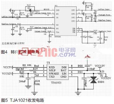
The BCM needs to drive the front steering, rear steering and side turn signals at the same time. The front and rear turn signals are 24W/12V and the side turn signals are 6W/12V. After comparison, the intelligent high-end power switch BTS5246 is selected to realize the control of the turn signal. The chip integrates power drive, current detection, temperature sensor and other circuits to provide dual high-end output, output power up to 480W, which can fully meet the power requirements of turn signals, and provides complete fault detection and protection. Compared with the discrete components, the circuit is simpler and the operating frequency is higher, which greatly reduces the board space and improves the EMC performance of the module. The BTS5246 based turn signal control circuit is shown in Figure 4.
In the load control function of the BCM, not only the power drive to the load but also a certain time characteristic is required. In the turn signal control, the switching control of the power chip BTS5246 needs to be realized, and since the steering lamp has two kinds of blinking frequencies of 80 times/min and 160 times/min depending on the working mode, the timing and timing functions need to be realized.
In the load control of BCM, whether it is a cycle flashing turn signal, an alarm warning light, a PWM start and extinguish keyhole light and indoor ceiling light, or a door lock motor and a window motor, etc., the power switches are all IO controlled. The way, and many have time characteristics. Thus, the control signal of each load corresponds to two variables, which respectively represent its IO control and time characteristics. Take the left turn signal control as an example:
#dene FASTFLASH 1
#dene SLOWFLASH 2
#dene SHUTDOWN 3
Extern uchar LnLgt_Cyout;
Extern Bool LnLgt_Port;
Where LftnLgt_Cyout represents the output of the left turn signal and its time characteristics, LftnLgt_Cyout=FASTFLASH indicates that the left turn signal flashes at a frequency of 160 times/min; LftnLgt_Cyout=SLOWFLASH indicates that the left turn signal flashes at a frequency of 80 times/min; LftnLgt_Cyout=SHUTDOWN indicates that it is off status. LftnLgt_Port is the IO port on the CPU that controls the left turn signal. It directly controls the power switch of the BTS5246. Its interface function is DrivePort (Driverport Drport, Bool Oper). Among them, Drport is the output control port macro definition, and Opera has DRIVEON and DRIVEOFF. The value controls the opening and closing of the smart power switch.
As the main node of the distributed body control system, BCM communicates with other nodes through the LIN bus. The LIN physical layer transceiver TJA1021 and the MCU on-chip peripheral UART are used to complete the LIN interface circuit design, as shown in Figure 5. TJA1021 is a LIN physical layer chip of Philips (Editor's Note: now NXP), with baud rate up to 20kbit/s, bus waveform shaping and level shifting function [3], high electromagnetic interference resistance and very low The electromagnetic emission can meet the demanding requirements of the automotive environment. It integrates the slave-side resistor internally. In the slave node application, the LIN bus impedance matching can be realized without external resistors. The BCM is the LIN master node. As shown in Figure 5, an external 1k host-side resistor is required to VEE.
The LIN bus data adopts the SCI format. By connecting the TXD and RXD of the TJA1021 to the UART transmit and receive pins of the MCU, the LIN data link layer can be implemented in software on the UART. Since LIN is physically single-wired, both transmit and receive are performed on the LIN line, so the transmission also triggers reception, so that the implementation of its data link layer can be unified into the receive processing function of the UART. This part can be implemented in the form of a state machine according to the format of the LIN frame [4].
As the LIN master node of the body control system, BCM schedules the transmission of LIN messages in a time-slicing manner. When the time slice arrives, the BCM sends the frame header including the interval field, the sync field and the PID [5]. Each node then decides whether to receive the data field or the data field based on the PID. The rotation of the time slice is implemented based on the schedule table, and the structure defined as follows implements management of the schedule entry.
Typedef struct
{
Uchar handle;
Uchar pid;
Uchar mode;
Uchar *data;
Uchar datalen;
Uchar ticks;
}l_sch_table_item;
The handle is the index of the schedule entry, which is incremented each time the time slice is rotated. When it is transferred to the schedule table, it switches to the schedule header and continues to rotate. The pid is the Protected ID of the LIN message, and the mode indicates that the frame data field is The BCM transmission is still sent by other nodes, data is the data field, datalen is the data field length, and ticks defines the time slice length, that is, the time interval between the frame and the next frame.
The LIN frame scheduling table is an array of l_sch_table_item structures. The time slice timing is determined according to the ticks of the current schedule entry. When the timeout occurs, the current time slice is switched, and the schedule entry is switched, so that the rotation scheduling of the LIN message is realized.
Conclusion
This paper analyzes the structure of the body control system for a certain vehicle. From the aspects of input signal detection, output control and LIN communication, the design and implementation of the vehicle body central controller are described. The controller is loaded and tested, running well and stable. , has a high practical value.
Plastic Package Diode.Among the electronic components, a device having two electrodes allows only the current to flow in a single direction, and many uses apply its rectification function. The Varicap Diode is used as an electronic adjustable capacitor. Most of the diodes have a current directionality that we often call the "Rectifying" function. The most common function of a diode is to allow only current to pass in a single direction (referred to as forward bias) and block in the reverse direction (referred to as reverse bias). Therefore, the diode can be thought of as an electronic version of the check valve.
Plastic Package Diode
Plastic Package Diode,High Frequency Diode,High Voltage Avalanche Diode,Plastic Package Zener Diode
YANGZHOU POSITIONING TECH CO., LTD. , http://www.yzpst.com