The circuit uses NMOS FET as the power output device, designs and implements the high-power DC motor H-bridge drive circuit, and performs closed-loop control on the 25D60-24A DC motor with rated voltage of 24 volts and rated current of 3.8A. The circuit has strong anti-interference ability and has strong applicability in the field of industrial control. Many semiconductor companies have introduced DC-specific driver chips, but most of these chips are only suitable for low-power DC motors. For high-power DC motors, integrated chips are expensive.
In the design of the DC motor drive circuit, the main considerations are as follows:
1. Function: Is the motor unidirectional or bidirectional? Need to adjust speed? For one-way motor drive, simply drive the motor directly with a high-power triode or FET or relay
That is, when the motor needs to rotate in both directions, you can use an H-bridge circuit consisting of 4 power components or a double-pole double-throw relay. If you do not need speed control, just make
It can be used with a relay; however, if speed regulation is required, PWM (Pulse Width Modulation) speed regulation can be realized by using a switching element such as a triode or a field effect transistor.
2. Performance: For the PWM drive motor drive circuit, the main performance indicators are as follows.
1) Output current and voltage range, which determines how much power the circuit can drive.
2) Efficiency, high efficiency not only means saving power, but also reducing the heating of the drive circuit. To improve the efficiency of the circuit, it is possible to ensure the switching state and prevention of the power device.
Stop common-mode conduction (a problem that may occur with H-bridge or push-pull circuits, where both power devices are turned on simultaneously to short-circuit the power supply).
3) The effect on the control input. The power circuit should have good signal isolation at its input to prevent high voltage and large current from entering the main control circuit, which can be used with high input impedance or
The optocoupler achieves isolation.
4) The impact on the power supply. Common-state conduction can cause a transient drop in the power supply voltage to cause high-frequency power supply contamination; large currents can cause the ground potential to float.
5) Reliability. The motor drive circuit should be as close as possible, no matter what kind of control signal, what kind of passive load, the circuit is safe. H-bridge drive circuit: The H-bridge motor drive circuit consists of four triodes and a motor. Because its shape resembles the letter 'H', it is called an H-bridge drive circuit.
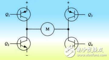
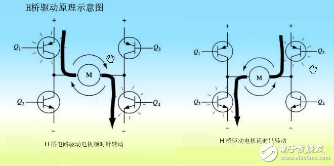
To operate the motor M, a pair of transistors on the diagonal must be turned on. For example, when the Q1 tube and the Q4 tube are turned on, the current passes from the positive pole of the power supply through the Q1 from left to right through the motor, and then returns to the negative pole of the power supply via Q4. The motor rotates clockwise. When transistors Q2 and Q3 are turned on, current flows from right to left through the motor, and the drive motor rotates counterclockwise.
The complete transistor H-bridge driver circuit, PWM1, PWM2, is the motor direction control input terminal, PWM1=1, PWM2=0, forward rotation, PWM=0, PWM2=1, the motor is reversed.
PWM1 and PWM2 are also the pulse width input terminals of motor speed regulation.
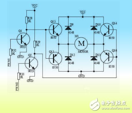
Transistors are the cheapest control method, but there is a significant voltage drop on the transistor, which will result in power loss and low efficiency. It is suitable for low voltage and low power applications.
The following figure shows the H-bridge drive circuit composed of FETs. The FET is the most efficient control method, but the price is high, and it is usually used in high-power motor drive applications.
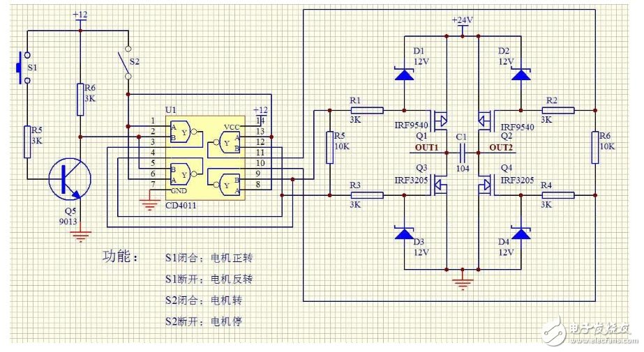
The above is a circuit composed of discrete components, which is troublesome in actual use and has a high failure rate. Usually integrated H-bridge driver chip, high integration, easy to use, high reliability. Such as L9110, L298N, LMD18200, TA7257P, SN754410, MC33886 and so on.
Closed Tricycle Electric Vehicle
Three-Wheel Electric,Enclosed Electric Vehicle,Three-Wheeled Electric Vehicle,Closed Tricycle Electric Vehicle
Jinan Huajiang environmental protection and energy saving Technology Co., Ltd , https://www.hjnewenergy.com