Introduction: This article introduces a soft and hardware design of a high-power dimmable color-illuminated LED that is remotely controlled by a mobile phone. As the client, the mobile phone Bluetooth communicates with the Bluetooth module HC-06 of the MCU control board to generate a four-way adjustable duty cycle PWM signal to control the high-power LED drive circuit. By adopting PWM dimming technology, one-way PWM wave is used to adjust white LED light to realize dimming, and three-way PWM wave is used to adjust high-power full-color RGB LED lamp to realize DIY coloring. The client adopts the Eclipse development environment, android programming, and the server uses the single-chip microcomputer to generate control signals to control the LED driver circuit, and the two parties communicate through the serial port emulation protocol. The experimental results show that the MCU can receive the remote control signal of the mobile phone and flexibly adjust the brightness of the LED from 0 to 100%. The dimming brightness is 100-level and the DIY color of the full-color LED. There are 1 million color toning.
1 Introduction
With, on October 30, 2012, Philips sold the latest high-tech Hue series of LED lights on the AppleStore, and only sold it to Apple. The Hue series will be fully customizable and can be mixed with 16 million colors of light through a red, blue and green primary color LED in a light bulb. The whole process is completely controlled by the app on the iPhone. This has led to new thinking on the development of intelligent light control, and relevant domestic people have also conducted research. Considering that Hue adopts WiFi wireless control, and domestic WiFi is not popular, this study adopts more common Bluetooth technology, uses mobile phone Bluetooth and MCU communication to generate adjustable duty cycle PWM wave signal to control LED drive circuit to realize LED dimming and DIY coloring.
2. Pulse width (PWM) dimming technology
PWM dimming is a dimming technique that uses a simple digital pulse to repeatedly switch the LED driver. The application's system only needs to provide wide and narrow digital pulses to simply change the output current to adjust the brightness of the LED. The advantage of PWM dimming is that the dimming range is large. As long as the bandwidth is sufficient, any analog value can be encoded using PWM. PWM dimming can accurately control the brightness of the LED while ensuring the chromaticity of the LED illumination.
2.1 Pulse Wide (PWM) Dimming Principle
The human eye is visually inert, and the duty ratio is adjusted at a fixed frequency to achieve LED brightness adjustment. As long as the dimming ratio, that is, the PWM wave frequency is greater than 200 Hz, the human eye will not feel the flicker of the LED. The specific dimming is realized by controlling the brightness of the LED to control the brightness of the LED. From the viewpoint of electric power, it is to control the effective value of the current in a certain period. This method does not change the magnitude of the voltage and current while changing the magnitude of the current rms, thus ensuring the luminosity of the LED, which is not possible with analog dimming and thyristor dimming.
2.2 duty cycle
The duty cycle is the ratio of the time that a high level takes up within one cycle. The square wave has a duty cycle of 50% and a duty cycle of 0.5, indicating that the positive level takes 0.5 cycle.
Ts is the pulse period
Tw is the pulse width
The duty ratio τ=Tw/Ts×100.
The interpretation of the duty cycle can be summarized as follows:
1) In a series of ideal pulse sequences (such as a square wave), the ratio of the duration of the positive pulse to the total pulse period.
2) The ratio of the time taken by the pulse to the total time during a continuous working period.
3) In the periodic phenomenon, the ratio of the time of occurrence of the phenomenon to the total time.
That is, the ratio of the effective time of the circuit to release energy to the total release time.
2.3 dimming ratio
The dimming ratio is calculated as follows:
Foper=working frequency
Fpwm=dimming frequency
Dimming ratio=Foper/Fpwm
In fact, it is the minimum effective duty ratio of dimming, such as Foper=100khz; Fpwm=200Hz, the dimming ratio is:
100k/200=500.
3. Bluetooth module
3.1 Bluetooth technology foundation
The founder of Bluetooth is the Swedish company Ericsson. Bluetooth technology is an open global specification for wireless data and voice communications. It is based on low-cost short-range wireless connections and establishes a special connection between fixed and mobile device communication environments. Data sharing between mobile phones via Bluetooth has become common sense, turning mobile phones into remote controls brings infinite convenience to people's lives. [1]
Bluetooth technology consists of three parts, including Bluetooth radio technology, Bluetooth protocol stack and Bluetooth interoperability.
3.1.1 Bluetooth Radio Technology
The Bluetooth radio works in the global 2.4 GHz zISM (industrial, scientific, medical) frequency band, supports full-duplex transmission, and uses the IEEE 802.15 protocol. Bluetooth device is ready to use, anti-interference ability, easy to use [2]
3.1.2 Bluetooth protocol stack
The Bluetooth stack contains a software stack and a hardware stack. The Bluetooth hardware protocol stack is provided by Bluetooth hardware, and the Bluetooth software protocol stack is implemented by software. The Bluetooth software stack provides the Java Bluetooth API for use by program openers.
3.1.3 Bluetooth Interoperability
Bluetooth interoperability includes three aspects: 1 universal access profile defines device management functionality; 2 service discovery application profiles define service discovery content; 3 serial profiles define interoperability devices and analog serial cable capabilities 3.2 HC- O6 Bluetooth module
BC04 external 8M Flash, with EDR module HC-06 for civilian grade, compatible with HC-04 industrial grade. Among them, the TX pin of the HC-06 module is connected to the P3.0 pin of the STC15F204EA microcontroller, and the RX pin is connected to P3.1. The HC-06 module receives the data sent from the mobile phone, and then communicates with the MCU through the serial port TR and TX pins.
Bluetooth 2.0 with EDR, 2Mbps-3Mbps modulation, built-in 2.4GHz antenna, external 8Mbit FLASH, low voltage 3.3V operation (3.1V~4.2V) 30~40MA fluctuation when pairing, pairing completed communication 8MA, optional PIO control standard HCI port (UART or USB), digital 2.4GHz wireless transmit, CSR BC04 Bluetooth chip technology, adaptive frequency hopping technology, Bluetooth Class 2 power level, operating temperature -25 to +75, co-wave interference 2.4MHz, launch The power is 3dBm and the effective control distance is 10m.
4. Mobile APP design
4.1 Bluetooth connection related program design
First, initialize the local Bluetooth device and establish the LocalDevice class, including obtaining the local device instance, Bluetooth name, setting the discovery mode, and obtaining the discovery agent. Create a public int BTS_Init() function to implement Bluetooth initialization judgment, find the default Bluetooth device, and turn on Bluetooth.
Start the Bluetooth device search, create a public voidBTS_StartScan() class function, start looking for the slave Bluetooth device, register the search function, and create a public int BTS_ConnectToDevice(String DeviceAddress) class function to connect to a specified Bluetooth device.
Create a public int BTS_SendDates (Stringbuffer) class function to send the string to the connected Bluetooth device, create a public int BTS_Finish () class function to end the Bluetooth communication, and finally create a BroadcastReceiver privatefinal BroadcastReceiver mReceiver = newBroadcastReceiver () to receive the ACTION_FOUND broadcast.
4.2 Control signal related program design
First create a class public class PwmcontrolActivity extends Activity{} for control signals, which contains the class function public voidonCreate(BundlesavedInstanstan state){}, which sends the control signal class function public void onStop TrackingTouch(SeekBar seekBar){}.
Create class class InitThread extends Thread{}, implement resource loading thread, create public InitThread(PwmcontrolActivity act){} function for conversion between four signals, realize public void run() thread body interface with Bluetooth program, The class function public booleanonKeyDown(int keyCo de, KeyEvent event) used for software exit.
5. Single chip control signal design
5.1 hardware circuit design
System block diagram shown in Figure 1, the hardware circuit uses STC15F204EA microcontroller as the main controller, CH-06 Bluetooth module TXD and MCU 11 pin P3.0 connection, RXD and P3.1 connected to achieve Bluetooth serial communication connection, from P1.0, P1.1, P1.2, P1.3 four ports output four-way adjustable duty cycle PWM signal, using an L298 chip to isolate the MCU control signal and LED power supply drive, avoiding the load capacity of the MCU Weak shortcomings to achieve high power LEDs.

5.2 Programming
The main function flow chart is shown in Figure 2. After defining the relevant variables and related function declarations, design the serial communication function, set the timer 1 interrupt, the interrupt function is the duty cycle control function, and then design the data receiving function, when the serial port service function When receiving the data, the data is sent to the data receiving function, and then the received character data is transformed into characters by the character transformation function, and then which signal is controlled by the flag iCommdType, and when there is no flag signal, the loop is checked continuously. Check the corresponding flag signal, and then perform the duty cycle adjustment function. The communication between the Bluetooth module and the MCU is realized by using the analog serial port. The serial port is the standard configuration: the baud rate is 9600. Write a serial port initialization function void UART_INIT(), initialize the relevant Flag, and register, then write interrupt receive function void tm0 () interrupt 1 using 1, receive the data sent by the serial port. Set the timer 1 interrupt and write the interrupt service function void tm1()interrupt 3 using1 to implement the duty cycle control of the PWM. Write the data receiving function char GetUartData(), send the data received in the interrupt receiving function here, wait for the receiving data function void WaitForChars(unsigned chariCount, char *Dest) to send the mobile phone by calling the data receiving function char GetUartData() The data is loaded into the defined variable array, and then the character conversion data is converted into a number by the character transformation function unsigned int GetCmdType(char*Commd), and the PWM wave is controlled by the flag, and then the corresponding data is transmitted to the control. The duty cycle interrupt service function changes the output of its duty cycle.

6. Results display
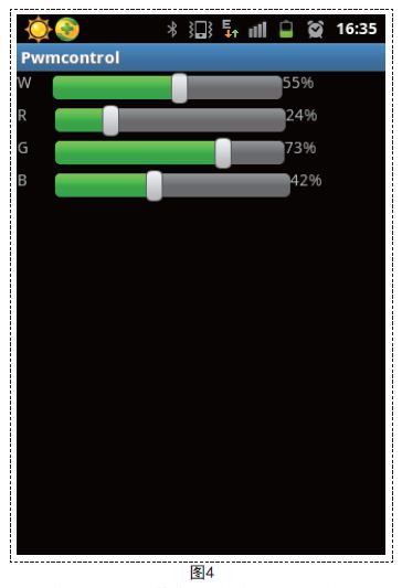
6.1 Mobile phone interface
As shown in FIG. 3, in which W adjusts white light, there are 1 million combinations from 0 to 100R, B, and G, and each combination corresponds to one color, and the color of the LED is adjusted by changing the combination of RBGs.
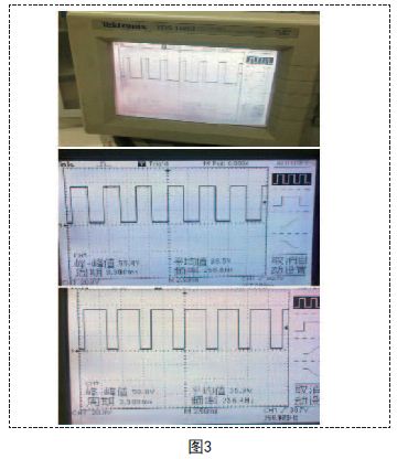
6.2 PWM wave output effect
As shown in Figure 4, this is the control signal of one of the PWM waves. The duty cycle is controlled by the mobile terminal, and the waveform is measured by an oscilloscope.
6.3 Actual dimming effect
Several combinations of color matching effects are selected as shown in FIG.

MOSO Class II Programmable LED Driver supports 0-10V, PWM, timer step dimming or DALI control from 75W to 320W. It can reprogram the output by a software or infrared controller. Class II outdoor Driver is IP67 waterproof, with build-in surge protection. It provides a Dim-to-off mode with low standby power. MOSO Class II Programmable power uses extruded-metal housing and fully glue-potted for good dissipation.


MOSO developed Class II Programmable LED Driver series with special isolation design for global market especially for the Europe. All Class II LED Drivers are certified with CCC, CE, TUV, ENEC and CB standards.
MOSO has set several distributors in Europe, United States, Latin America, Asia and Australia. All MOSO Class II Programmable power suppliers provide 5 years global warranty. In case of any failure, customers can get replacement either from MOSO directly or any one of MOSO distributors.
MOSO always dedicates to providing professional outdoor lighting solutions. Please feel free to contact our sales team if you need any support!
Class II Programmable LED Driver
Class II Programmable LED Driver,Class II Programmable Dimmable Driver,Dim-to-off Class II Programmable Driver,Class II Programmable Outdoor LED Driver
Moso Electronics , https://www.mosoleddriver.com