1 Introduction
With the increasing energy and environmental issues, traditional incandescent lamps are being replaced on a large scale around the world. Although a large part of the compact fluorescent lamp, the concern about the mercury content of the lamp of the energy-saving lamp (which may cause pollution to the environment) and the need for greater energy-saving potential have led more and more users to turn to the LED lamp. The latest LED lamps consume less than 80% of the energy consumed by incandescent lamps and do not contain toxic substances. According to market research firm iSuppli, LED-related global sales will continue to grow strongly. Although the global economic recovery is slow, it is estimated that the market will reach approximately $14.6 billion in 2013.
With the widespread use of energy-saving lamps rich in electronic devices, consumers have begun to see frequent failures of such products. The potential life of LED lighting is greatly extended and provides better reliability. The question is whether the electronic drive used in the LED lamp also achieves the same life and high reliability. Poorly designed products may ruin the LED lighting industry, and the design of an excellent LED lighting system can last up to 500,004. However, unless the electronic device part can also have a long life and high reliability, the advantages of LED lighting will not be realized.
In design and production, it is important to understand the service life of the product and the reliability of the product are two very different concepts, although it does not matter, but they are often confused. Lifetime is the length of time before a user can expect a single product to work properly until the product is unsuitable for use. Reliability is used to reflect the failure rate of a batch product. It can be expressed in terms of MTBF (mean time between failures) or the reciprocal of failure rate. The life of 50000d means that this product can serve 50,000 hours. The 50,000-hour MTBF means that for every 1000 products, every 50 hours, from a probabilistic point of view, in theory, people will see a random failure. These two concepts are very important for the successful implementation of LED lighting.
2 life
Estimating the life of any product is primarily about determining the wear mechanism of all electronic components and then finding the shortest component life. For most power supplies, including LED drivers, the shortest life component will be electrolytic capacitors. The electrolyte in the capacitor will volatilize with different operating temperatures and working times, and the capacitor ripple current will also affect the lifetime. Although electrolytic capacitors may vary from manufacturer to manufacturer or from component to component, the life of a typical electrolytic capacitor can generally be expressed by the following formula [1]:
 (1)
(1)
Where: L: - the result of the life calculation;
k - the coefficient determined by the RMS ripple current of the capacitor and the operating voltage, which can be a value or a function;
Lo—life data provided by the capacitor manufacturer under specified standard conditions;
Ts—the surface temperature of the capacitor provided by the capacitor manufacturer under specified standard conditions;
Ta - Capacitor surface temperature under target operating conditions.
With this formula, optimizing life design can be quite simple. The first thing is to choose a high quality, long life capacitor. Second, engineers should strive to reduce the RMS ripple current flowing through the capacitor, as well as the operating voltage. So choosing a capacitor requires reducing the ripple current and voltage to get enough design margin. However, excessive selection of high-profile capacitors will result in the use of larger, more expensive products resulting in increased product costs. However, insufficient design margin can greatly damage the service life of the product. The industry believes that the most effective way is to reduce the surface temperature of the capacitor. The surface temperature of the capacitor is determined by the surrounding operating environment temperature, the heat dissipation capability of the driver, and the amount of heat generated. For a particular existing design and application, the primary determinant of temperature will be drive efficiency and heat dissipation. In other words, high efficiency and low thermal resistance design can significantly increase their service life. Efficiency has a greater impact on temperature than many people think. For example, efficiency from 95% to 85% does not mean that the loss will only be 10% different, but the corresponding increase of 3.3 times, and these losses are converted into heat in the drive. Infineon has invested heavily in research and development to improve the efficiency of LED drivers. In the popular EUC-150S (150W constant current output) series, the 220V AC full load efficiency is 92%, and the loss is only 13W. As the output power gets higher and higher, only 1% of the efficiency difference can see completely different power losses. Figure 1 shows the relationship between efficiency and loss.
Since the products of different designs can have significantly different efficiencies, the temperature inside the drive housing can vary greatly. As reflected in equation (1), a 10 °C temperature difference can be doubled. Even though the assumed thermal design is the same, this means that the thermal resistance from the capacitor to the air is the same, and drivers of different efficiencies will inevitably result in different capacitor temperatures, thus resulting in very different lifetimes. Still using the 150W product as an example, the relationship between efficiency and lifetime is shown in Figure 2.
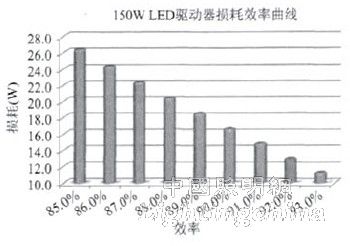
Figure 1 150WLED driver loss efficiency curve
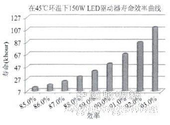
Figure 2 150WLED driver life efficiency curve
However, even if the driver is highly efficient, if there is no good heat conduction or convection design, the limited power loss will result in high temperatures of the internal electronic components. The use of a good thermal conductive potting material and a solid aluminum alloy casing can greatly reduce the thermal resistance from the electronic component to the environment. In this way, the drive can achieve a life of 87,000d at an ambient temperature of 45 ° C. This is better than most LED drivers on the market today, which will greatly improve and facilitate the application and development of LED lighting projects.
3 reliability
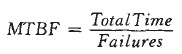
Reliability is a concept related to the failure rate of a product operating under its rated conditions during its rated service life. The usual way to express reliability is MTBF, which is the average time between failures of the product. Although reliability and longevity are often calculated in hours, they are still quite different concepts. Equation (2) shows the calculation of the mean time between failures, which is the total running time divided by the number of product failures.
 (2)
(2)
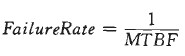
As an example, a sample population of 1000 products produces a total of 24,000 hours per day. If this group has 4 failures in one month of work, the MTBF of this product is (1000 units × 24 hours / day × 30 days) / 4, that is, 180,000 hours. To provide another example, if the MTBF of the product is 300,000 hours, it is likely that these products will fail at an average of 300 hours for 1000 simultaneous operations. The number of these products is 10,000, and it is foreseeable that there will be one failure every 30 hours. It must be clear that a product with an MTBF of 300,000 hours does not mean that any particular product will have a life expectancy of 300,000 hours. There is another way to understand reliability, it is to see its failure rate. Equation (3) shows that the failure rate is only the reciprocal of MTBF.
 (3)
(3)
When determining the life of a product, just find the shortest component and calculate its life. However, when determining the reliability of a product, it is necessary to understand the failure rate of each component, which may lead to product failure and expect a combined failure rate.
The predecessors have spent a lot of time on the evaluation of the reliability of electronic equipment. The most common of these methods is MIL-HDBK-217 [2], which is commonly used in military equipment. It is considered as a standard reliability prediction method and is a reliability prediction method used by Infineon. Another common method is the Telecordia [3] reliability prediction model. Often, the evaluation of military equipment is less conservative than the second Telecordia business method, ie, the lifetime value is reduced. These two methods are called "calculated" reliability, rather than being actually experimented with running a large number of individuals. In fact, it is difficult to derive the value of MTBF by the latter. MTBF is used to measure the reliability of a product because it makes it possible to use the same method for effective comparison under the same conditions.
In fact, the challenge for drive manufacturers is to produce the most reliable products under certain scale and cost constraints. There are several key factors in reliability design. The first is the choice of the design of the main power stage topology. The reliability of a semiconductor component is usually determined by the operating junction temperature. Flyback and LLC half-bridge topologies like zero-current soft-switching can be used to minimize the switching losses of power semiconductors, thereby increasing the efficiency of the semiconductor and the overall drive and reducing the temperature. The second is to consider the selection of high-quality components and to ensure proper stress margin for components. For example, design a 20% operating voltage margin for high voltage electrolytic capacitors and a 10% peak voltage margin for semiconductor components to ensure a reliable design. Third, the protection circuit can make the product survive under extreme conditions, including various abnormal overcurrent, short circuit, over/under voltage or overheat. In addition, a surge suppression circuit is required to prevent lightning damage. Fourth, as mentioned earlier, we are back to efficiency and thermal design issues. Since temperature has a direct and significant impact on semiconductor reliability such as MOSFETs, integrated circuits and optocouplers, we have to put the efficiency of the drive once again at an important position. Figure 3 shows how efficiency affects the average MTBF of a 150W product.
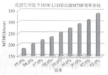
Figure 3 MTW efficiency curve of 150WLED driver
The last important issue with regard to reliability is the elimination of high failure rates during the initial stages of product completion. The concept of product reliability is only valid for the life of the product. In fact, the life of the product itself includes the time from the completion of production to the factory. But for the user, the service life is only started after leaving the factory. Figure 4 shows a well-known "bathtub" curve. The y-axis of this figure is the failure rate of the product, and the x-axis is time. Most foreign manufacturers refer to the high failure rate period that has just begun production as infantmortality and then enter the service life of the product, the flat bottom of the curve. Finally, as the product reaches its rated life, the failure rate begins to rise. The challenge for producers is to ensure that these products have a high period of failure before leaving the factory. In order to do this, Infinet has adopted a rigorous double aging for all products. Each product was subjected to an aging test for 1 to 2 hours before filling. Then, after the final potting assembly, all products run at high loads and temperatures for a period of time ranging from 4 to 12 hours, which is determined by the failure rate of the product during the aging process.
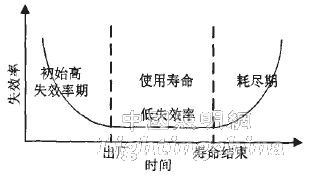
Figure 4 "bathtub" curve
4 Conclusion
Understanding life and reliability is critical to LED driver design. Life and reliability are more urgent for projects such as LED lighting that require long-term, uninterrupted work to pay off. The long life of the power supply makes the use of the lamp lower, and the high reliability makes the maintenance cost of the LED lamp lower, which forms a virtuous cycle of return on investment. There are many factors that must be considered to achieve this, but in this article we can see efficiency as a key indicator, to some extent further elaborate the importance of LED drive power. How LED driver power meets the requirements of today's lighting projects, it also takes a lot of time for in-depth research and analysis to ensure that long-term use and energy conservation goals are achieved.
Edit: Cedar
Features
â—† Designed For Water and Dust Tight(IP67)
â—† Small Compact Sizeâ—† UL&ENEC&CQC Safety Approvals
â—† Long life & high reliability
â—† Variety of Levers
â—† Wide Range of wiring Terminals
â—† Wide used in Automotive Electronics,Appliance and Industrial Control etc.
â—† Customized Designs
Dustproof Micro Switch,Micro Switch Company,Long Lever Micro Switch,Micro Selector Switch
Ningbo Jialin Electronics Co.,Ltd , https://www.donghai-switch.com