A shaft angle coding data acquisition system based on PCI soft core is studied to realize the real-time measurement and control of the angular position of the servo system. PCI interface logic is implemented using an FPGA device. The FIFO storage unit and the shaft angle conversion control logic implement a high-speed shaft angle conversion using a resolver-digital conversion module, and a corresponding WDM driver is designed. The acquisition board is used in the measurement and control system of LabWindows. The data sampling rate reaches 27 r/s and the data transmission rate reaches 132 MB/s.
0 Preface
In industrial control servo devices, high-precision real-time measurement and control of angular position quantities is a key technology. The shaft angle conversion module is an angular quantity/digital converter whose function is to convert the analog signals of the resolver and the synchromesh machine into digital signals. Compared with the common A/D code, the shaft angle coding adopts positive and negative The signal is encoded, with strong anti-interference ability and fast conversion speed. With the development of FPGA technology, the PCI interface can be implemented on the FPGA. Memory and logic control functions. Due to the flexible programmability of the FPGA, the PCI interface can be optimized according to the card function without having to implement all PCI functions, which can save the system logic resources and achieve a compact system design. This article describes a method for implementing a PCI interface board for angular high-speed acquisition using a shaft angle converter and an FPGA device from Altera Corporation.
1 system hardware design
The shaft angle data acquisition card is mainly composed of a shaft angle conversion device (RDC converter). The FPGA device is composed of EPF10K30. Its functional block diagram is shown in Figure 1, the sine of the input resolver. The cosine signal is converted into digital by the RDC converter, and the output precision is 14 bits. The FPGA implements the PCI bus interface function and the control logic function, and the internal is mainly composed of the PCI_MT32 macro unit and the FIFO memory.

The RDC converter implements the resolver signal to digital conversion, which works on the positive side of the resolver output. Cosine signal amplitude modulation signal, the angular amount information is included in the amplitude of the sine wave, and defines:
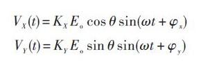
Where VX(t) and VY(t) represent sinusoids. The cosine signal has amplitudes of KX Eo cos θ and KY Eo sin θ, respectively. In the amplitude expression, only sin θ and cos θ vary; the reference amplitude Eo and the gain factors KX , KY are constant.
In the AC signal, positive. The ratio of the magnitude of the cosine signal carries the angular amount information, that is, the ratio of the equations (1) to (2):
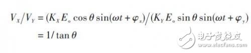
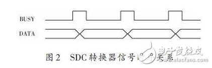
The angular amount is obtained from the tangent function tan θ in the equation (3). In the RDC converter, a continuous tracking conversion mode is adopted, and its conversion timing is as shown in FIG. 2, in which "BUSY" is a converter "busy" signal, and "DATA" is a data signal. When the "BUSY" signal is high, the converter is in the tracking transition state, the data signal "DATA" is in an unstable state of change; when the "BUSY" signal is low, the conversion is over and the data signal "DATA" is stable. Status, which can be read. In order to achieve continuous acquisition of the angular amount, according to the timing relationship of the converter, a FIFO memory is designed by the FPGA, and the data is triggered by the falling edge of the busy signal. The EPF10K30 has a 12 288-bit memory unit that can be designed by the user as a ROM.RAM or FIFO type memory. Using the parameterized dual clock FIFO macrocell LPM_FIFO_DC, the design data width (LPM_WIDTH) is 14 bits, and the data volume (LPM_NUM-WORDS) is 64 for the dual clock FIFO memory due to data read. The write is controlled by the rising edge of the clock, so the busy signal of the converter is reversed as the write clock signal (wrclock), the read clock (rdclock). read. The write request signal and the clear signal are controlled by the computer through the PCI interface.
Portable Electric Burner,Electric Cookers,Counter Top Cooking Tools,Electric Iron Burner
Shaoxing Haoda Electrical Appliance Co.,Ltd , https://www.hotplates.nl