1 Isolation requirements in traffic applications
This article refers to the address: http://
Hybrid and electric drive systems used in cars, trucks and motorcycles have created new and previously unknown challenges in the transportation industry. The original 12V voltage network now needs to be supplemented with a battery power supply of 400V or higher, which is a device that supplies power to electronic devices, also known as a power supply, which provides the power required by all the components in the computer, thus for automotive OEMs and system modules. The supplier has put forward a series of new requirements. Such as high voltage battery, DC/DC converter
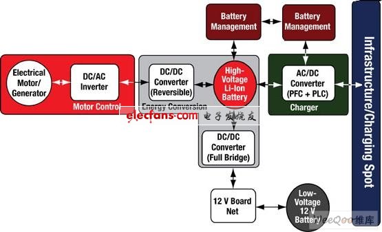
Figure 1: Typical system architecture for electric vehicles.
Automotive and transportation applications have different requirements for isolation than industrial applications. Solid and reliable is of course necessary, and magnetic "noise" must also have strong resistance. The high power level in the car (such as a 100 kW motor operating at 400 V, meaning 250 A operating current) will generate a strong magnetic field in the car that must be properly handled. The parts used must be long enough to meet the life expectancy requirements of the vehicle; for example, must meet the decades of use requirements for large-scale transportation applications. Products for the automotive environment will drive the quality of automotive applications (Q1) and operate over the -40 to +125 °C operating temperature range.
At the same time, cost pressures in these areas will drive higher system integration requirements, so single-chip products with isolation, such as CAN transceivers, ADCs or gate drivers, offer advantages.
2 different digital isolation technologies
In principle, there are four different methods of digital isolation: , capacitive and RF. The first three methods are described below.
The main advantage of optical isolation is that light is immune to electric or magnetic fields and has the potential to deliver static signals. At the flipside of the isolation layer, the operating frequency (transmission speed) of the optical isolator is limited by the relatively slow nature of the LED. For hybrid/electric vehicle applications, the limited lifetime of optical isolation is a major drawback. Over time, the efficiency of the LED will decrease, requiring a larger signal drive current (usually starting at 10 mA), so this optical isolation will not function as time goes by.
Inductive isolation uses a change in the magnetic field between the two coils to enable communication across the isolation barrier. One advantage of the inductive isolation method is the difference between common mode and differential transmission, which means that it has good noise immunity. The disadvantage of this approach is that it can be due to distortion of the magnetic field, which is common in motor control environments for hybrid/electric vehicle applications.
Capacitive isolation utilizes the electric field variation across the isolation barrier. The benefits of capacitive isolation are greater immunity to magnetic fields and longer system life. Capacitive isolation is similar to the transmission speed of the inductive isolation method.
However, the disadvantage of capacitive isolation is that there is no differential signal (ie, the signal and noise share the same channel). In addition, as with the inductive isolation method, they cannot directly transmit static signals (which must be encoded with the frequency signal first).
3 isolation products
An example of a capacitive isolation method is the ISOxxxx series from Texas Instruments. Figure 2 is a simplified architecture diagram of the ISO72xx system. The ISOxxxx component integrates two bare crystals placed on separate leadframes, as well as transmit and receive chips, in a single package. The two bare crystals are connected by only one bonding wire. The actual isolation function implemented on the receiver is based on silicon dioxide (SiO2, glass) with copper and doped silicon as the substrate electrode capacitor (Figure 3). The use of SiO2 offers the advantages of high reliability and long life.
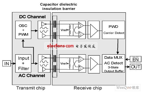
Figure 2: TI's ISO 72xx series architecture diagram.
Figure 3: TI's ISO72xx series of dies, with the silicon dioxide isolation on the receiver chip on the right.
Both channels allow both DC and AC communication, and it also has a fail-safe feature.
The basic AC channel uses the input signal and, after filtering, transmits the signal through a differential pair consisting of isolated capacitors. Then, the input of the Schmitt trigger on the receiving chip is detected, and finally the received signal is output through the output buffer. It achieves very high speed transmission, slight pulse width distortion and short transmission delay, but does not transmit DC signals.
- Only housing, small parts are not included
- Professional repair skill is needed to install this part, or search installation guides on youtube to make sure you can operate it, we will not take responsibility for any damages to this part nor your device caused by wrong installation
- With SIM card tray, mute switch, power button, volume buttons
Test:
· On-off flex cable;
· Flash;
· Charging Port & Charging flex cable ;
· Back camera;
· Volume button;
· Mute button;
· Buzzer & Vibrator;
Features:
· 12 Months warranty.
· Flex cables are all original.
· Exquisite craftsmanship.
· Inner Package: Anti-Static Bags & Transparent Air Bubble Bags ; Outer Package: Carton Box Also In Lined With Foam;
iPhone 6S/6S Plus Housing Assembly
iPhone 6S Back Cover Housing Assembly,iPhone 6S Back Cover,iPhone 6S Assembly Replacement,iPhone 6S Plus Back Cover Housing,iPhone 6S Plus Back Cover,iPhone 6S Plus Replacement
Shenzhen Aokal Technology Co., Ltd. , https://www.aokal.com