"Compared with early manual connected desktop equipment, users can save 90% of radar test time by using NI PXI modular instruments and a secondary surveillance radar (SSR) automatic test system developed by LabVIEW. Compared to other traditional box-based The automatic test equipment of the built-in instrument saves 60% of the cost for users while saving time effectively. "
-Vishwanath Kalkur, Captronic Systems Pvt Ltd
challenge:
Using PXI modular instrument and LabVIEW software to develop secondary monitoring radar automatic test system.

Figure 1 The overall architecture of the SSR automatic test system
solution:
By using NI PXI modular instruments and NI LabVIEW FPGA modules, a user-defined and extensible solution is designed to test all radar functions.
Unlike the primary radar, the secondary surveillance radar (SSR) can collect information including identity, altitude, and country code by establishing a two-way communication connection to calculate the distance and azimuth of the target aircraft. SSR is used by engineers in military aviation and civil aviation. The former usually includes an enemy-friend identification system.
SSR can work in multiple modes to obtain target information. The system sends out an interrogation pulse signal of 1030MHZ through the bidirectional rotating antenna of the radar. If the target finds the interrogation pulse, its inter-frequency radar transceiver will return a frame pulse of 1090MHz. The radar of the ground base station will generate an interrogation pulse and request the target to return information such as identity, altitude, country code, etc. according to mode A / 3A, mode C, or mode S. Based on the query response, the aircraft responds with a standard response pulse format. The system can calculate the distance and azimuth of the target based on the speed-distance relationship and the position of the rotating antenna relative to the north or the direction of travel.
Today's radars need to pass rigorous testing before being deployed into military or civil space equipment. We have developed an automatic test system based on NI PXI modular instruments to achieve radar functional testing. The system can also test the physical parameters of the receiver (RX) and transmitter (TX), including: receiver bandwidth, receiver sensitivity , Transmitter power, transmitter pulse and other parameters. Functional tests include: communication between the target simulator and the radar at a frequency of 1090MHz, video signal detection, radar scan converter display based on the synthesized TTL logic video signal, and LAN communication. Return pulses from the target and multi-target simulators are either stationary or moving along the orbit. Figure 1 is an overall block diagram of an automatic test system connected to SSR.
System overview
The system we developed includes an NI PXI-1042 eight-slot chassis and an NI PXI-8196 embedded controller. By setting the radar to work in the transmission mode or the reception mode, the transmitter or receiver function is realized; at the same time, the external antenna signal and the azimuth counting pulse are generated and simulated by the FPGA platform. The target return pulse is generated by the NI PXI-5671 vector signal generator (VSG), and the pulse frequency is 1090MHz. The system obtains the video demodulation signal from the receiver through the oscilloscope board used for the receiver function test. The system can also obtain RF pulses with high power transmission through the NI PXI-5661 vector signal analyzer (VSA) to analyze the signal power and pulse parameters of the transmitter. The synthetic TTL video data generated by the radar processing unit is collected through the digital signal input port of the FPGA. These data are used by the radar scan converter to display the target's distance, bearing, information code, altitude, and country code in polar coordinates. Figure 2 shows the detailed schematic diagram of the automatic test system connected to the SSR.
Each trigger pulse and synchronization pulse are synchronized with the RF interrogation pulse generated by the SSR. Due to the built-in transceiver module in the radar, in order to protect the device, in the RX test, we chose to turn off the transmitter of the radar. The TX and RX ports share the same physical port connected to the antenna. VSA (Vector Signal Analyzer) and VSG (Vector Signal Generator) are connected to this same physical port, so that you can replace the function of the antenna to generate and collect 1090MHz and 1030MHz RF signals.
Measurement parameters
TX parameters
The TX outside the radar is connected to the vector signal analyzer of the automatic test system through an attenuator. Radio frequency transmission is performed by a sinusoidal pulse with a threshold, the pulse width is approximately 1us, and the pulse repetition time (PRT) is 5ms.
· TX frequency stability (1030MHz + 0.03MHz)
· Pulse peak power (2.0KW)
· Pulse repetition period (ms)
· Output power mode and PRF stability
· Output power selection and segmentation
· Pulse spacing
· Pulse waveform
· Pulse duty cycle (0.01% to 66%)
· Pulse width (us)
· Pulse rise time (ns)
· Fall time (ns)
· Spectrum
RX parameters
The RX in the radar receives the RF pulse generated by the vector signal generator. This pulse is synchronized with the trigger / sync pulse. Each synchronization pulse is synchronized with the interrogation pulse. After the vector signal generator and the trigger port of the FPGA receive synchronization pulses, the vector signal generator outputs RF pulses. The RX video output is connected to the oscilloscope board to measure the following RX parameters:
· Receiver sensitivity
· Receiver bandwidth
· Receiver dynamic range
· Receiver frequency stability
· Phase difference measurement
· Receive chain operation sensitivity (STC)
· Receiving chain side lobe suppression (RSLS)
function test
During functional testing, the system generates antenna analog signals similar to azimuth and ACP. The system will simulate different azimuth angles and distances of multi-targets moving statically or along the trajectory, and display the azimuth angles and distances of different frequency radar transceivers in the scan conversion application.
Target simulation
We can test the function of RX through target simulation, this process will use vector signal generator based on synchronization signal. In this case, ATE (Automatic Test Equipment) will act as the target signal generator from the antenna. Each query is synchronized with the trigger pulse on the FPGA through the trigger terminal connected to the vector signal generator. Users can simulate the target by configuring information such as distance and azimuth. When the target is ready for simulation, once the azimuth counter data reaches the FPGA and the radar has obtained the next synchronous trigger signal, the vector signal generator will generate the target's response RF pulse. The user can choose to set the code and mode of the response. At a specified distance and azimuth angle, a pulse that follows a certain mode will be generated. The target object can be simulated as static motion and along the trajectory. The user can configure different routes of movement. The system can simulate multiple targets with different distances and azimuths in the same vector signal generator. According to the requirements of users, different coding modes are applied to different response pulses. The response pulse is a pulse sequence with a width of 450ns and an interval of 1us. The structure of each target's response frame has F1 and F2 pulses at the beginning and end of the sequence. The number of pulses in each response frame structure is determined by the query mode selected in the GUI. Each synchronization pulse can have different modes of response according to the selected query mode. The three response pulses are separately configurable and can be generated by the vector signal generator according to each synchronization pulse. Figure 5 depicts the response pulse generation with distance delay, bearing, and code simulation.
Radar scan converter
The system obtains and processes TTL video signals from the radar through the FPGA board. The target's response pulse is decoded by the radar's receiver. At the same time, the original video signal is processed in the radar's processing unit. This processor can provide energy Synthetic TTL pulse representing the response frame.
This frame structure is decoded in FPGA by individual pulses with precise width. Because the receiver will receive some noise signals from the antenna at the same time, it will produce some useless noise pulses in the required range. The designer has developed a new algorithm to eliminate the noise pulses and decode the real frame information. The FPGA then calculates the distance and bearing of the target based on the target's information code, altitude, and country code.
The system can receive synthetic TTL video, the format requirements are: real target obtained from the antenna, simulation target generated inside the radar, simulation target based on the interrogation pulse simulated by the vector signal generator.
Figure 4 shows the decoding process of the scan converter in FPGA. Figure 5 describes the process of ACP, northbound simulation through FPGA, trigger / sync pulse acquisition, response pulse simulation based on distance and bearing selection, TTL video signal acquisition, and decoding of response frames.
The modulated pulse generated by the vector signal generator contains a 1030MHz RF carrier.
Antenna simulation
The north mark pulse generated by FPGA and the ACP generated by FPGA digital IO can provide antenna simulation. The designer created a user-configurable GUI based on LabVIEW, set the pulse width, PRT, and the azimuth value calculated based on the deviation of the rotation angle relative to the north direction, in order to simulate the antenna parameters.
Software features
The designer has developed a series of modular, editable test sequences to test the overall functionality. Users can choose automatic or manual mode for individual parameter testing. Through the diagnostic panel, users can use PXI devices for retrospective or custom testing. Figure 6 describes the test series in the automatic test system.
Reduce radar test time with NI platform
Compared with the early manual connection of desktop equipment, users can save 90% of radar test time by using the SSR automatic test system developed by NI PXI modular instruments and LabVIEW software. Compared with other automatic test equipment based on traditional box instruments, while effectively saving time, this design can also save users 60% of the cost. In addition, the new system uses an NI PXI vector signal generator to replace the pulse generator and modulator, and the system can provide complete functional testing including target simulation, original video acquisition, target detection, etc., making it a closed loop Test system.
We plan to upgrade the system and use automatic switching to test the 6 redundant ports of the radar. To this end, we will use the NI PXI-2596 SP6T multiplexer to upgrade the system to avoid cables and connections that are too long.
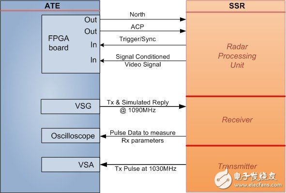
Figure 2 Detailed schematic diagram of SSR and its automatic test system 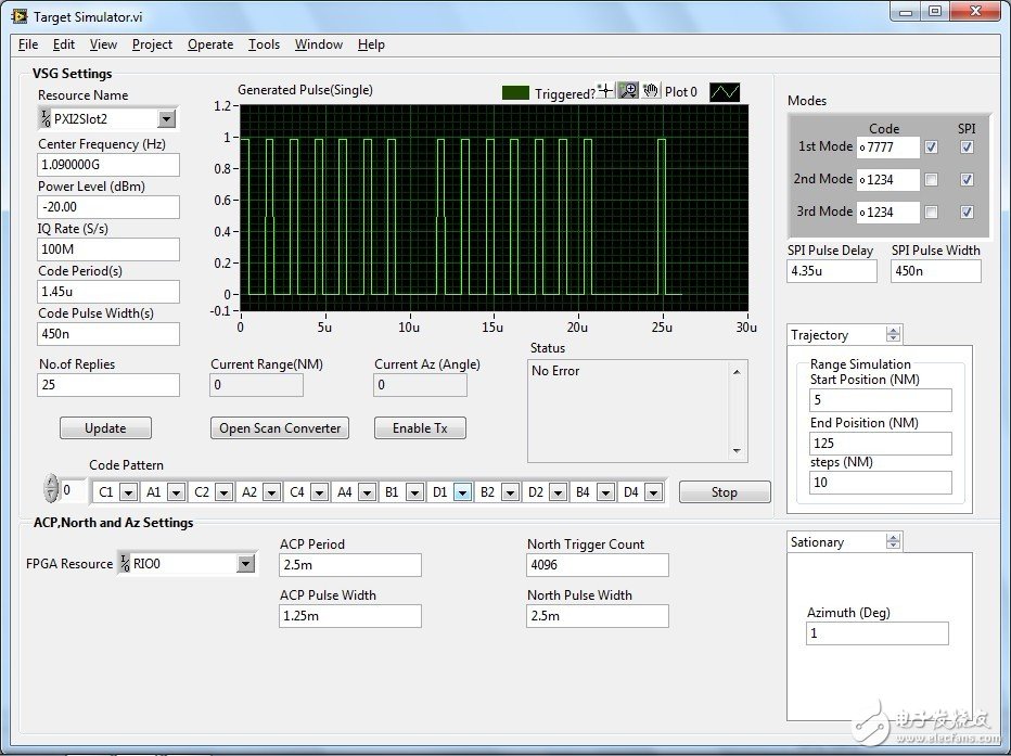
Figure 3 Target emulator software interface 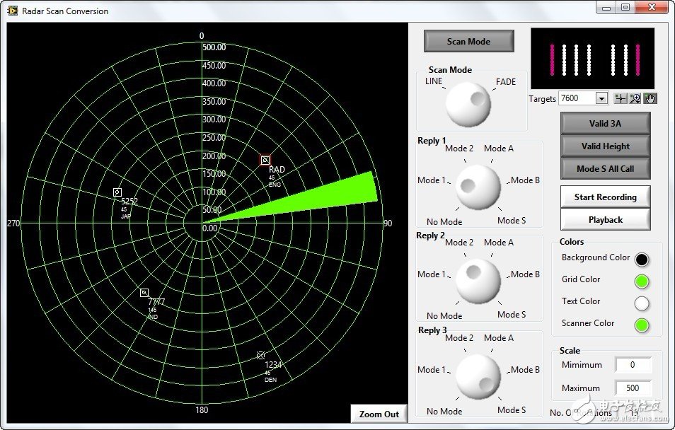
Figure 4 Radar scan converter 
Figure 5 Northbound, ACP trigger sync pulse from DUT, response frame simulation, synthesized SSRTTL video 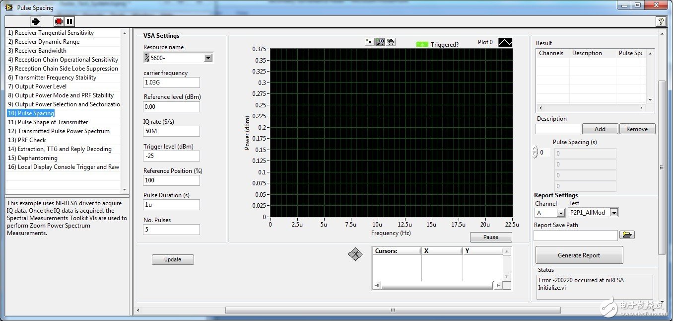
Figure 6 Test sequence
Infrared LED Lamps ( IR LED lamps) is LED with wavelength more than 680nm wavelength, the most frequently used infrared LED (IR LED) is 850nm IR LED, 940nm IR LED, 880nm IR LED, 730nm IR LED, 950nm IR LED, 810nm IR LED, 680nm IR LED, 780nm IR LED, 830nm IR LED and so on.
Infrared LED lamps(IR LED lamps) widely used for those "night-vision" cameras, IP camera, remote controls, Touch screen, intelligent monitoring, webcam, hunting camera, CCTV cameras, surveillance cameras and security system. For instance, 940mn Through-hole IR LED did a great job in night-vision. 850mn SMD IR LED did a great job in infrared touch screen.

Infrared LED Lamps,5Mm LED Infrared Lamps,850Nm Infrared LED Lamps,Infrared Emitting LED Lamps
Shenzhen Best LED Opto-electronic Co.,Ltd , https://www.bestsmd.com