0 Preface
Although high-power LEDs can't replace traditional light sources on a large scale, they have more and more applications in outdoor lighting. The advantages of LED's environmental protection, energy saving and high efficiency require a suitable LED driver to ensure the focus of this paper. A new method for designing a constant current driver for a DC system is introduced.
1 PWM switch constant current drive mode
LED drivers account for only a small fraction of DC lighting systems, but they are related to the reliability of the entire system. There are many kinds of LED drivers on the market, such as resistor current limiting type, constant voltage type, linear constant current type, PWM switching constant current type, etc. After comparison test, this circuit selects PWM switching constant current driving mode. In this way, the switching current of the power supply circuit and the energy storage inductor and the capacitor are used to form a high-efficiency constant current driving circuit, and the output current is constant, and the output DC voltage is within a certain range according to the load resistance. Change, load resistance is small, output voltage is low, the load resistance is larger, and the output voltage is higher. This constant current driving method adapts to the LED current type characteristic. When the temperature change or other factors cause the LED PN junction voltage drop to change, the constant current of the LED can be ensured, the LED will not be damaged, and the light can be delayed. decline.
2 circuit design principle
This design is a LED constant current driver with temperature protection, including high power LED light source, DC power supply, anti-reverse circuit, PWM control circuit, temperature detection circuit and freewheeling circuit. The DC power supply is connected to the PWM control circuit and the temperature detection circuit through the anti-reverse circuit, and the temperature detection circuit and the freewheeling circuit are respectively connected to the PWM control circuit, and the high-power LED light source is connected to the PWM control circuit and the temperature detection circuit. Among them, the DC power supply (DC12V) supplies power to the PWM control circuit and the temperature detection circuit through the anti-reverse circuit. The PWM control circuit and the freewheeling circuit provide a stable set current for the high-power LED light source, and the temperature detection circuit detects the high-power LED in time. The operating temperature of the light source, feedback control of the PWM control circuit, so that the high-power LED light source operates in a safe temperature range.
Referring to FIG. 1, a LED constant current driver with temperature protection includes a high power LED light source 6, a DC power source 1, an anti-reverse circuit 2, a PWM control circuit 4, a temperature detecting circuit 5, and a freewheeling circuit 3. The DC power supply 1 (DC12V) supplies power to the PWM control circuit 4 and the temperature detection circuit 5 via the anti-reverse circuit 2, and the PWM control circuit 4 and the freewheeling circuit 3 provide a stable set current for the high-power LED light source 6, the temperature detection circuit 5 Timely detect the operating temperature of the high-power LED light source 6, and feedback control the PWM control circuit 4 so that the high-power LED light source 6 operates in a safe temperature range.
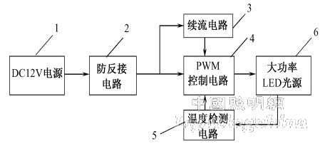
Figure 1 The composition of the constant current driver
Referring to Figure 2, the circuit is constructed as follows:
(1) DC power supply 1 (battery or solar photovoltaic power supply): DC12V.
(2) The anti-reverse circuit 2 is composed of D1 and C1, and its working principle is: the power supply is supplied with power through the unidirectional conductive diode D1 and the filter capacitor C1 for the PWM control circuit 4, the freewheeling circuit 3 and the temperature detecting circuit 5.
(3) The constant current circuit is composed of a PWM control circuit 4, a temperature detecting circuit 5, and a freewheeling circuit 3. Specifically, it is composed of U1, R1, L1, C2, D2, and LED1 to LED. The resistor R1 functions as a load loop current detection feedback, L1, C2, and D2 form a freewheeling circuit 3, and U1 is a PWM control circuit 4.
(4) The temperature detecting circuit 5 is composed of an integrated circuit U2, resistors R2 and R3, a temperature sensor RT, capacitors C3, C4, and C5. Among them, U2, R3, RT, C4, C5 form a multivibrator circuit, and the resistance value of the temperature sensor RT changes with the temperature change of the LED light source, thereby changing the duty ratio of the oscillation pulse of the multi-resonant circuit.
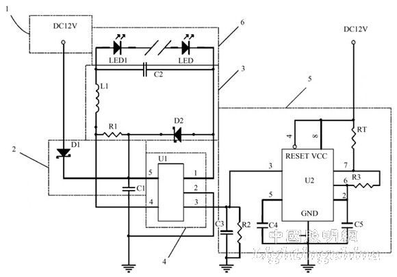
Figure 2 Schematic diagram of the drive circuit
The oscillation pulse of the output of U2's 3-pin output is sent to the 3rd pin of the PWM control circuit 4 (integrated block U1) through R2 and C3 filtering, thereby controlling the current value flowing through the LED light source. The current Io passing through the LED light source has the following The formula can be calculated as: Io=0.1RT/R3/R1. The temperature of the LED light source is controlled by the temperature sensor RT to limit the temperature of the LED light source to a safe setting range.
When the DC power source 1 is DC12V, the high-power LED light source 6 is connected in series by two 1W LEDs, and may also be in the form of one 1W LED or three 1W LEDs in series.
3 Conclusion
Through temperature protection and constant current function, this circuit design slows down the impact of high temperature and high current on high-power LED light source, thus extending the service life of LED; it is especially suitable for DC lighting system with high-power LED as light source.
Edit: Cedar
li ion 3s battery pack, 9v lowest, 12.6v highest. can be made to reguated stable 9v/10v/11v/12v.
3s battery, 3s lipo, 3s Lipo Battery , 9v Battery ,10.8V Battery Pack,11.1V Rechargeable Battery,12.6V Lithium Battery, 3S Lithium Ion Battery.
9v Battery
9v Battery,10.8V Battery Pack,11.1V Rechargeable Battery,12.6V Lithium Battery
Asarke Industry Co., Limited , https://www.asarke-industry.com