This article refers to the address: http://
The transmission of high-definition digital television in a limited bandwidth imposes higher requirements on video, audio compression coding and channel coding, and in the case of terrestrial transmission, various attenuations and interferences in the wireless environment are also inevitable, while considering To the receiving needs in the mobile environment, it is necessary to introduce the latest technology of wireless communication in a new generation of terrestrial digital television transmission systems. The combination of digital TV broadcasting and modern digital communication technology has enabled traditional TV media to be reborn on the basis of communication networks.On the basis of comprehensively absorbing the advantages of high-definition digital TV standards in foreign countries, Tsinghua University has completely developed and completed the digital digital multimedia television broadcasting transmission protocol DMB-Tî–„ and applied for a service invention patent. At the 2nd China International Hi-Tech Fair, held in Shenzhen, Tsinghua University has fully demonstrated this technology and has been recognized by many experts.
Cadence's system-level design and simulation software SPW Signal Processing Worksystem was used in the DMB-T system design. In the large-scale system design, only the implementation of algorithm and system-level optimization can greatly improve the system performance, because it has more optimization space than the underlying optimization.
Take Cadence's software tools as an example. The corresponding system-level design flow is shown in Figure 1.
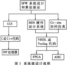
Traditional electronic design processes usually start with hardware description language VHDL or Verilog and perform hardware-related optimization directly. The optimization of real high-level algorithms is very limited. This kind of design idea is applicable when the system scale is small and the corresponding algorithm is mature. Now the scale of electronic design is getting bigger and bigger, the complexity is getting higher and higher, and the large workload is concentrated on the previous high-level algorithm development. Previously, the previous process will no longer meet the needs.
The system-level design method refers to the first use of special system-level design tools such as SPW for algorithm development. Unlike traditional design methods, system-level design tools can free users from the cumbersome hardware implementation and concentrate on corresponding The algorithm is developed to verify the feasibility of the system algorithm and obtain performance indicators through simulation. After the algorithm is determined, the designer converts the result of the system-level design into the hardware description language VHDL or Verilog through the hardware design system (Hardware Design System) and the hardware-software co-simulation interface Co-Sim, and then implements it with FPGA or ASIC.
1 Ideal system simulation Digital TV transmission system involves many subsystems of modulation, coding, transmission and reception, decoding and demodulation, but the modeling of channel is of great significance to system performance. The core technology adopted in DMB-T is OFDM Orthogonal Frequency Division Multiplexing, which is much better than DVB-T in Europe in channel estimation and synchronization algorithms. In the design methodology, we can first consider the ideal transmission channel for channel noise and interference non-existence, focusing on the design of modulation, demodulation, coding and decoding systems, and first establish an ideal system model.
The description of the modulation method, the error correction outer code, the interleaving coding in the time domain and the frequency domain, and the error correction inner code are as shown in FIG. 2.
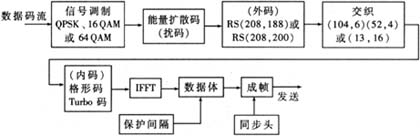
Several optional modes are provided in the modulation and coding process, such as RS208î–„200 with high data rate or RS208î–„188 with high protection rate. This is mainly to provide different priorities and protection levels for different data to achieve the purpose of layered transmission.
The ideal system simulation is mainly to verify the correctness of the system signal transmission process. This design is a digital TV design, so the most intuitive method is to input an MPEG2 code stream to the transmission system, observe the received code stream at the system output and play it with MPEG2 player, so that you can see the entire data in the ideal system. The design of the channel is completely correct. With SPW, you can easily adjust parameters and replace related modules so that the overall performance of the system is optimal. The corresponding receiving process is the process of decoding, deinterleaving, and demodulating. Which mode is selected and what parameters are selected can be simply modified in the design, and the parameters and modules can be continuously adjusted to optimize the overall performance of the system.
It can be seen that DMB-T has strong forward error correction capability. In theory, the FFT in the receiver using OFDM modulation can smooth out various pulses of short duration, so the pulse interference in the time domain should be more robust; and the high protection rate RS 208 188 code and 104 2 , The interleave coding of the 52 4 mode also makes the DMB-T highly resistant to pulse interference.
DMB-T uses OFDM orthogonal multi-carrier modulation, which uses a large number of sub-carriers for data transmission. Single-frequency interference can damage a small number of sub-carriers, and the lost data can be easily corrected by error correction coding. Therefore, DMB-T also has strong resistance to single-frequency interference.
According to the general comparison standard, the carrier-to-noise ratio tolerance Eb/No of DMB-T to SDTV is 7.8Db and the carrier-to-noise tolerance of HDTV is 10.8dB under AWGN channel. Here the idea of ​​layered transmission is used, and there are two different results, but even for HDTV, DMB-T has outstanding anti-noise performance.
2 Gaussian white noise AWGN and multipath performance studies need to add multipath channel model and corresponding channel estimation and processing module after establishing ideal system. Because multipath modeling and channel estimation algorithm are relatively complex, simulation is time consuming. In addition to the parametric simulation, a simulation of the MPEG2 code stream was performed. The simulation interface obtained with SPW is shown in Figure 3.
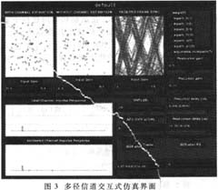
The buttons and scroll bars in the diagram can be adjusted with the mouse to achieve interactive adjustment of system parameters. The upper right corner of the figure corresponds to the wireless channel multipath model defined by the United States and Europe. In the design, click the corresponding button to join the corresponding multipath model, and the corresponding simulation result can be obtained. For the specified multipath model, the signal-to-noise ratio can be adjusted to observe different simulation results. In the user simulation, the adjustable multipath button in the upper right corner of Figure 3 can be used to arbitrarily set the multipath model and set the multipath parameters in the right half of Fig. 3 and complete the corresponding simulation. Figure 3 corresponds to the US standard mpath_b channel model, and the lower left part is the channel estimation result made by the system based on the received signal. It can be seen that the two are very matched.
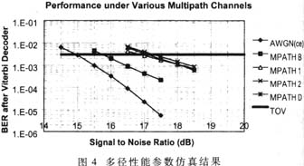
In the DMB-T system, the time domain insertion sequence is used, and the channel impulse response is used for channel estimation, and the impact on the data transmission rate is 7%. Gaussian noise and time-varying channels have little effect on the proposed channel estimation algorithm, and because the algorithm has been optimized and improved in the development and design process, the system has outstanding performance in anti-multipath interference, and it is mobile. The receiving environment is especially suitable. The simulation results for the system parameters are shown in Figure 4.
3 System Synchronization Performance Simulation In order to evaluate the synchronization performance of the system, a special synchronization circuit, including transmitter, Code acquisition, STR, AFC, FFT and Channel Estimation, was designed to fully realize the system synchronization function. The interactive interface of the simulation is shown in Figure 5.
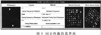
The Time ms field in Figure 5 shows that the actual system operation time is different from the simulation time. The following fields represent the frequency offset, time offset, and the frequency offset and time offset estimated by the design system synchronization circuit. After the Code Acquisition Lock" field changes from red to green, the right half of the field represents the corresponding constellation before and after the channel estimation. From the simulation, the entire code synchronization acquisition time is only 5ms, which is much shorter than the synchronization time of similar systems. And the correction of time offset and frequency offset has reached the design requirements.
Both the time domain and the frequency domain information are utilized in the DMB-T.
The sampling clock is synchronized, and the carrier synchronization is performed by using the spread-spectrum pseudo-random PN sequence. The acquisition time of the signal is shortened to 5 ms, and the time domain and frequency domain correction can be completed within 20 ms, and the system realizes synchronization.
4 Process of design implementation There is no system-level simulation in the previous design process. It is usually modified and optimized after the hardware is completed. The algorithm optimization and parameter adjustment at the system level are not only low cost, but also efficient. Very high. Optimal performance and theoretical optimal parameters are obtained by continuously adjusting system parameters and improving related algorithms. As can be seen from the foregoing, the use of SPW software for system-level design and simulation allows the designer to focus on the algorithm implementation and optimization of the system without having to think too much about the specific hardware implementation.
When these system-level simulations are all completed, as shown in the flow chart of Figure 1, the CPU design system HDS, Verilog simulation software Verilog-XL and NC-Verilog, SPW and Verilog co-simulation software are used in SPW. The system-level design is converted to the RTL-level Verilog hardware description language, which is implemented by FPGA and PCB layout. After field testing of the prototype prototype implemented by the FPGA, the complete design can be made into an application-specific integrated circuit ASIC.
crawler tractors are versatile,domestic initiative and technology leading. Hydraulic controlled differential - brake turn to technology , 360 degree steering wheel control and spin turn are our company`s unique advantages. In addition, our products also have the superiorities of triangular track drive, low grounding pressure and better Paddy field performance. Our company has iron Crawler Tractor and Rubber Crawler Tractor, which two main products. Every products have different types. These products are of high efficiency, long operating life. and low fuel consumption. Our crawler tractors are easy switching between hydraulic infinitely variable speed and mechanical transmission.
Model
NF-Y602
NF-Y702
NF-Y802
Size
length×width×height(mm)
2900×1360×1500
3430×1590×2300
Weight
(Kg)
1700
2200
Minimum Ground Clearance
(mm)
260
410
Engine
Model
3G25TC
YD4CZ70C1
YD4SZ80C1
Form
Electronic
injection.vertical.water-cooled.four-stroke
Rated power(kW)
44.1
51.5
58.8
Fuel
Diesel
Rated power(r/min)
2400
Starting method
Electric start
Steering Brake System
Steerig system type
Planetary differential steering
Brake system type
Wet friction steering
Drive Train
Clutch type
Single-chip single-acting
Transmission type
2(mechanical file)+2×2(hydraulic stepless speed change)
Transmission shift model
Gear shift
Walking System
Rack form
Rigid frame type
Track pitch section×number×width
90×46×280
90×50×350
The theoretical speed of each file(km/h)
Forward:mechanical block:4.86; 8.65
Hydraulic block:0-5.75; 0-10.24
Back:0-5.75;0-10.24
Working Device
Lifter type
Semi-split
Tillage depth control
Force adjustment
PTO form
Type1,non-independent
Power output shaft speed(r/min)
624/960
Model
NF-702
NF-802
NF-902
Size
length×width×height(mm)
3690×1500×2400
3690×1650×2560
Weight
(Kg)
2255
2450
Minimum Ground Clearance
(mm)
395
420
Engine
Model
YD4CZ70C1
YD4EZ80C1
YD4EZ90C1
Form
Electronic injection.vertical.water-cooled.four-stroke
Rated power(kW)
51.5
58.8
66.2
Fuel
Diesel
Rated power(r/min)
2400
Tarting method
Electric start
Steering Brake System
Steerig system type
Planetary differential steering
Brake system type
Wet friction steering
Drive System
Clutch type
Single-chip single-acting
Transmission type
Eight forward speed+ reverse gear
Transmission shift model
Gear shift
Walking System
Rack form
Rigid frame type
Track pitch section×number×width
90×51×400
90×56×400
The theoretical speed of each file(km/h)
Ahead:1.22;1.80;2.92; 3.84;5.50;8.08;13.13;17.25
Backward:0.97;1.43;2.32;3.04;4.36;6.41;10.42;13.68
Working Device
Lifter type
Semi-split
Tillage depth control
Force adjustment
PTO form
Type1,non-independent
Power output shaft speed(r/min)
720/1000
PTO shaft spline and the outer diameter mm
8×38
Model
NF-Q502
NF-Q602
NF-Q702
NF-Q802
Size
length×width×height(mm)
3430×1590×2300
Weight
(Kg)
1715
1890
1930
1990
Minimum Ground Clearance
(mm)
395
Engine
Model
YD4C50V1
YD4JZ60C1
YD4CZ70C1
YD4SZ80C1
Form
electronic injection.vertical.water-cooled.four-stroke
Rated power(kW)
36.8
44.1
51.5
58.8
Fuel
diesel
Rated speed(r/min)
2400
Starting method
Electric start
Steering Brake System
Steerig system type
Tooth embedded clutch-braking
brake system type
Wet friction type
Drive System
clutch type
Monolithic single-acting
transmission type
Main transmission (hydraulic stepless speed + mechanical gear)
+auxiliary transmission 2 files
transmission shift model
Gear shift
Walking System
rack form
Rigid frame type
track pitch section×number×width
90×46×350(with side teeth)
90×50×350(with side teeth)
the theoretical speed of each file(km/h)
Hydraulic:high0-9.2;low0-6.2
mechanical:8.2;5.3
Working Device
lifter type
Semi-split type
tillage depth control
Bit adjust(optional force adjust)
PTO form
Type1, non-independent
power output shaft speed(r/min)
620/960
PTO shaft spline and the outer diameter mm
8×38
If you have any questions, please contact with us directly. Crawler tractors are produced
by our company with high quality and good appearance. Welcome you can visit our factory.for
inqury,Please send mail directly to us!
Crawler Tractor
Crawler Tractor,Light Crawler Tractor,Tractor With Low Ground Pressure,Multifunctional Crawler Tractor
Hunan NongFu Machinery&Electronic.Co., Ltd. , http://www.nfagmachine.com