introduction
With the continuous development of society and economy, the environment and resources are becoming more and more prominent. It is estimated that by 2020, the total annual water demand will reach 90 billion cubic meters, and the water shortage will reach 15 billion cubic meters. The shortage of water resources has become To limit the important factors of China's economic and social development, the country vigorously advocates energy conservation and emission reduction, and encourages research and development of water-saving and energy-saving equipment. The water-saving technology of the bathroom began in the late 1980s and early 1990s. In the initial stage of water-saving technology, digital logic circuits and analog electronic technologies were widely used to realize water-saving control functions. Since the 21st century, bathroom water-saving technologies have adopted advanced technologies. The infrared detection technology and the single-chip control technology have greatly improved the water saving rate. At present, there are many technical defects in the water-saving equipment of the bathroom, that is, the flushing is not timely, the accidental flushing and the leakage of the toilet are frequent, resulting in low water saving rate and poor sanitation.
In order to achieve a conservation-oriented and environment-friendly society, the future water-saving equipment for the bathroom will be developed in the direction of high water-saving rate, environmental protection, integration and intelligence. Based on this, a weighted intelligent water saving system based on statistical and fuzzy control theory is designed. It uses the improved infrared detection unit to accurately collect data; the AT89C2051 single-chip microcomputer is used as the hardware platform to construct the main controller of signal processing and control, to process the detection data, and to determine the real human flow in real time; the main water injection and the weight control Water injection ensures that the main control unit can flush the toilet quickly after issuing the flushing command. The test results show that the performance indicators of the system have reached the design requirements, and the water saving rate has increased to 88%.
1 Control technology In order to ensure that the water in the water tank can be quickly discharged after the main control unit issues the flushing command, the water-saving system adopts the weight control technology, and the power-controlled flushing function is controlled by the main water injection and anti-leakage control unit. The control unit is implemented. The main water injection unit determines that the solenoid valve is activated when the water tank is completely empty according to the state of the low water level detector of the water tank, and stops when the main water injection reaches 95% of the total capacity of the water tank, which is the low water level of the water tank. Due to the long-term accumulation of impurities in the water and the tight sealing of the siphon valve and the water tank of the water tank, the water staying for a long time will cause the water level to drop due to leakage. In view of this, the anti-leakage circuit is designed to replenish the water so that the water level of the water tank is always maintained in the water tank. 95% of the total capacity. The main control unit processes the toilet information in real time and issues the right water injection command. This part of the water injection only accounts for 5% of the total capacity of the water tank, which takes 1 to 2 s. After the water is injected, the water in the water tank has filled the entire water tank and reached the position where the siphon valve is opened. This rapid control technology for flushing is called weight control technology.
2 system hardware design The system uses AT89C2051 single-chip microcomputer as the main control unit of the system, which can realize infrared signal processing, solenoid valve water injection control and LED display; combined with C language software programming, it realizes flushing control which is consistent with the actual situation. The two-level program security measures enrich the system functions and improve the stability of the system.
The system consists of two main control units, Figure 1 is the main control unit structure diagram, complete infrared signal processing, delay selection and execution of the flush subroutine. Among them, the improved infrared monitoring can sense the moving organism, the high water level can detect whether the water level of the water tank reaches the siphon point, and the delay selection is to manually select the delayed flushing time when the toilet is in the low peak period; the LED can display the main controller work in real time. status.
This article refers to the address: http://
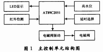
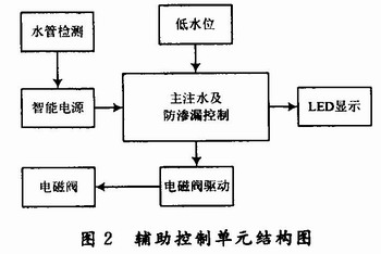
Figure 2 shows the auxiliary control unit, which completes the water-free power-off, main water injection and anti-leakage control. When the pipe network is broken, the low water level detection tank is always waterless, so the main water injection control circuit always turns on the solenoid valve, so the intelligent power supply is designed to disconnect all circuit power sources except the water pipe detection when there is no water. The low water level detects whether the main water injection reaches 95% of the water tank. The main water injection control unit controls the solenoid valve according to it; the anti-leakage control unit keeps the water tank at 95% water level.
2.1 Intelligent power supply design The intelligent power supply system structure includes digital +5 V power supply circuit, analog +5 V power supply circuit, and water-free power-off control circuit. The system structure frame is shown in Figure 3.
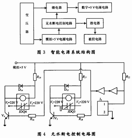
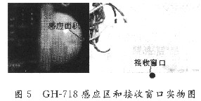
When the water-free power-off control circuit detects no water, control two relays JDQ3, JDQ4 disconnects the normally closed contact, cuts off all circuit power supply except the water pipe detection, which not only protects the solenoid valve, but also saves energy. After the pipe network resumes water supply, the water-free power-off control circuit can quickly restore the circuit power supply, and the system enters the normal working state. The circuit diagram of the water-free power-off control is shown in Figure 4.
2.2 Infrared monitoring design Infrared monitoring uses GH-718 human body sensing module to sense the organism and output high level. The GH-718 human body sensing module has two trigger modes: repeatable trigger and non-repeatable trigger. In order to accurately calculate the number of people entering the toilet, the system is set to repeatable trigger mode. However, the effective detection range of the GH-718 human body sensing module is 110°, and the detection distance is up to 7 m. When the human body moves in this area, the same toilet holder has multiple infrared triggers. In order to reduce the false triggering and even reduce the false trigger to zero, the system sets the GH-718 human body sensing module in the casing, and the bottom of the casing is centered to open a circular hole with a diameter of 2 mm. After the above improvement, the infrared monitor only inductively moves the human body to generate infrared pulses on one line, which greatly improves the monitoring accuracy, and the false detection rate is reduced to 0.2%, as shown in Fig. 5.
2.3 Main water injection and anti-leakage control circuit design The main water injection and anti-leakage control circuit is not controlled by the main control unit. It judges whether water injection, main water injection and anti-leakage control are carried out by the high and low level sent by the low water level detection device. The circuit is shown in Figure 6.
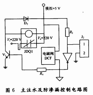
When the water level of the water tank is not low, the low water level detecting device is low level, and after a non-gate, it becomes a high level, so the transistor V1 drives the electromagnetic valve to close due to saturation conduction to perform main water injection. When the water level of the water tank is reached, the water level detecting device of the water tank sends a high level, and after a non-gate, it becomes a low level, so that the transistor V1 is turned off, and the main water injection control circuit turns off the electromagnetic valve to stop the main water injection.
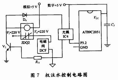
2.4 Right water control circuit design right water injection is based on AT89C2051 as the core of the main control unit implementation circuit shown in Figure 7. When the power injection control circuit is coupled with the microprocessor, the optocoupler is coupled. The advantage is that the coupling of the optocoupler can block the interference of the interference signal such as the spike of the relay and the opening and closing of the solenoid valve to avoid the interference of the microprocessor, thereby avoiding The main control unit has unstable working performance due to interference, which reduces the probability of accidental flushing and leakage flushing. The signal flow is: the right water injection command is sent from the P3.2 port, and the V2 is sent to the optocoupler IC4 to drive the V2 to conduct, the control relay is closed and the electric shock is normally turned on, and the electromagnetic valve is opened to fill the water.
3 system software design This system takes AT89C2051 single chip as the core, in order to realize the signal processing and control function of single chip computer, the program is divided into 6 modules: 3 min timing module, infrared pulse counting module, high and low peak period decision module, delay selection module , water level detection module, solenoid valve module, the main program flow of the microcontroller is shown in Figure 8.
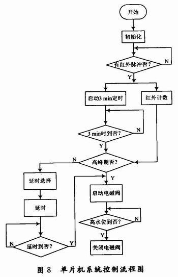
The 3 min timing module is started when the infrared detection is sent to the first infrared pulse through the P3.1 port, and the infrared pulse counting module counts the infrared pulse in the 3 min timing time. When the 3 min timing is up, the 3 min timing module and the infrared counting module are reset to zero. After that, the 3 min timing module and the infrared counting module are started again when the next infrared pulse arrives. At the same time, the infrared pulse count value of the infrared counting module is sent to the high and low peak period decision module.
The high and low peak decision module has two functions: when the infrared count value meets the peak number within 3 minutes, the solenoid valve is activated to fill the water; when the infrared count value does not meet the peak number within 3 minutes, the delay selection module is started.
The delay selection setting has a friendly man-machine dialogue interface, which is composed of a delay selection program and 7 sets of mechanical switches preset manually set outside the machine. When the delay time is up, the solenoid valve is opened to make a wish. In order to eliminate the instantaneous spikes generated by the switch opening and closing, the infrared counting is interrupted, and a detonating pulse circuit is designed on each set of switches.
The water level detecting module detects whether the right water injection reaches the siphon point of the siphon valve, that is, the high water level position, and when the water is injected to the high water level, the water level detecting module activates the electromagnetic valve module to close it.
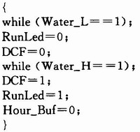
Due to space reasons, some C language source programs are given here: 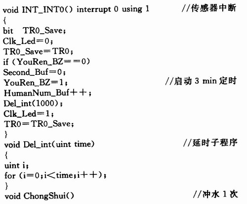
Through many experiments under the actual working environment, the system runs well, and the false detection rate of infrared monitoring is less than O. 2%, flushing lag time is less than 1 s. Table 1 shows the annual water consumption of the water-saving system at the detection period of 3 min, and the water consumption of the ordinary flusher.
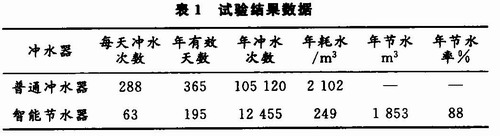
It can be seen from Table 1 that the power-saving intelligent water-saving device has a water-saving rate of 88% when the detection period is 3 min, which greatly saves water resources and conforms to the original intention of the design.
4 The power-controlled intelligent water-saving scheme proposed by the conclusion effectively solved the technical shortcomings of the existing water-saving products, such as untimely flushing, accidental flushing, and flushing, which greatly improved the water saving rate and obtained satisfactory results. With the development of signal processing technology, this kind of weight-controlled intelligent water-saving device based on pyroelectric infrared moving sensor and single-chip microprocessor will have a very broad application prospect.
Din rail ups have 36W and 60W, output current have 3A and 5A. din rail ups with 7AH battery, being available for charging battery
Features:
Wide input range: 100-240V, 50/60Hz.
Easy for the installation and can move in the rail follow CCTV when working
Cooling by free air convection
LED indicator for power on
Protection: short circuit, over current, overload, over voltage.
Efficiency 85%
100% full load burn-in test
3 years warranty
Product application:
Suitable for home automation, CCTV, security camera and led lighting
Din-Rail Power Supply,Din-Rail Power Supply Ups,Din Rail Power Supply Applications,Din Rail Power Supply 48Vdc
Dongguan Xiaoerduo Electronics Co., Ltd. , http://www.steadysmps.com