2016, VR first year, heavyweight manufacturers such as oculus, HTC, Sony, etc. have launched or announced their own consumer hardware products to seize the consumer market. I believe many of the VR enthusiasts have already started a Virtual reality device. Among these hardwares, the Oculus Rift CV1 (hereafter referred to as "CV1") is undoubtedly one of the most eye-catching hardware products. After all, it has a big event such as Facebook's $2 billion in 2014.
As we all know, Oculus Rift uses active optical positioning technology, how is it achieved?
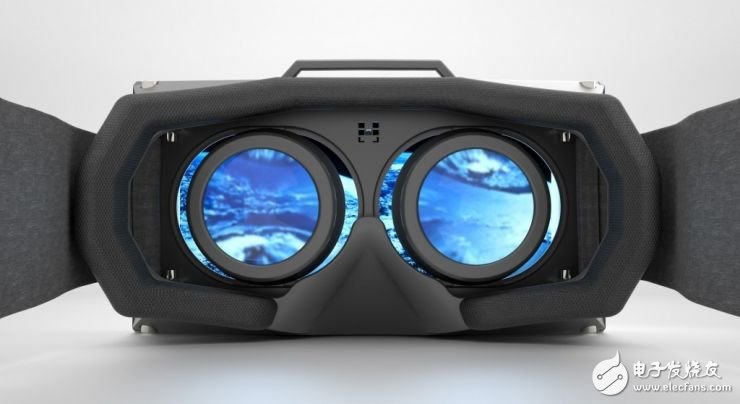
(via:nukethefridge.com)
Basic implementation process:
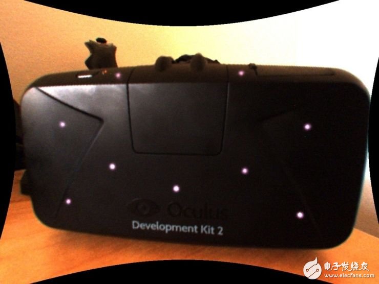
There are hidden infrared lights (that is, marker points) hidden on the Oculus Rift device. These infrared lights can emit infrared light and shoot in real time with an infrared camera. After obtaining the infrared image, the image captured by the camera is transmitted to the computing unit, and the useless information is filtered by the visual algorithm to obtain the direction of the infrared light, and then the PnP algorithm is utilized, that is, four non-coplanar infrared lamps are used. The position information on the device and the image information obtained at the four points can finally incorporate the device into the camera coordinate system, fit the three-dimensional model of the device, and monitor the player's head and hand movement in real time.
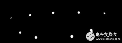
Note: You can see the following picture, pay attention to the red dots above.
Next I will introduce you to my reasoning process and some details of the algorithm.
| LED lights on the head display
In the previous article, I mentioned that we need to use the position information of four non-coplanar infrared lamps on the device for positioning. If we want to know the position information of different infrared lamps on the device, we must be able to distinguish different infrared lamps. .
Why do you say this? If you don't distinguish between infrared lights, then when DK2 moves in space, the number of times that the camera will be associated (the process of optimal pose matching) will be very large after the camera captures the spot. , give a list:
1) If there are N prediction image points and M <<= N observation image points, there is N! /(NM)! Possible association
2) For N = 40 and M = 20 (for the number of DK2 LEDs), there is a correlation of 3.3 & TImes; 1029, so even a computer can't get results quickly.
Obviously, DK2 must use some a priori way to distinguish the light spots. Then the question comes, how is DK2 distinguished?
I have seen an article speculating that DK2 is distinguished by the LED lights, but it is not. Because it is relatively simple to distinguish by the LED light, because the light and the light are most easily distinguished, but this method has a defect that it is impossible to distinguish whether the LED light caused by the posture change is blocked or the LED light itself is extinguished. Therefore, DK2 does not use this method, but uses the strength of LED lighting information to achieve. Let's observe the picture taken with a grayscale camera:
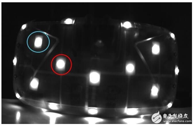
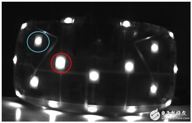
Comparing the two figures above, you can see that the size of the bright spots has changed. It can be seen that the red part is larger in Fig. 2 and the opposite in blue. Let's take a look at the detailed approach. It must be said here that in the process of speculating the specific practice, I mistakenly thought that DK2 directly judged the spot size, and then judged the ID of the LED light according to the law of the multi-frame image, but in fact DK2 uses the difference method to judge the spot size. I am here to briefly introduce you to my reasoning process.
First of all, I took a lot of photos with my own camera and observed that if I took the camera at a frequency of about 60HZ, the image will repeat every 10th.
I will first give the spot a number, as shown below:
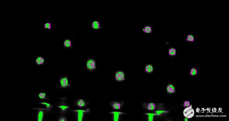
For example, the order of strength of the 2nd point can be identified by the naked eye: weak, weak, strong, strong, weak, strong, weak, weak, weak, strong.
So is this the case? How to express these strong and weak relationships in DK2?
First of all, the driver of the Windows SDK of the known SDK will send a start message to let the head display start to work;
Then, the driver will continue to receive the following information:
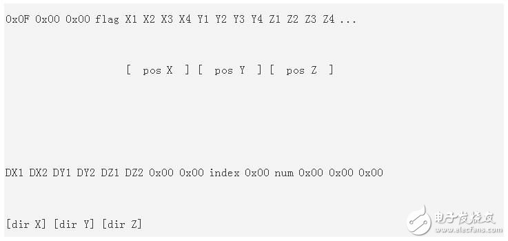
X1 X2 X3 X4 is a 32-bit number, which is the spatial coordinate obtained after image analysis (the principle is explained later), DX does not know what to do, but observe the above num, the conversion is 40, index starts from 1, Constantly increasing to 40, indicating that DK2 recognizes the LED lights one by one. In addition, the information is sent once every 17ms, which is similar to the shooting frequency of 60HZ. It can basically be determined that one LED is determined every 10 frames.
In order to fully determine this, another problem must be identified: synchronization.
If it is really the LED that changes the LED ID by 10 frames of different changes, then the camera must be synchronized.
This requires a synchronization signal to be transmitted to both the camera and the head display. If you know the timing of the synchronization, you know if it is 60Hz.
However, when I looked at the information of MT9V034, I found that the frequency of shooting was about 30HZ, but think about it, if you use differential detection, you can also use the 30HZ frequency to capture the change of light intensity. That is to say, DK2 does not directly judge whether the spot is large or small, but compares the spot of the current frame with the same spot of the previous frame. If it is larger than before, it is large, otherwise it is small. Then when a new frame arrives, the algorithm first extracts the bright pixel spots of the frame, as shown below. Ignore less than 10 pixels or not discs, and finally ensure that all the spots are from the large disc-like spots extracted in the previous frame and then compared.
Therefore, DK2 compares the spot of the current frame with the same spot of the previous frame, and then allows the camera to determine the ID of the LED light according to different changes of 10 frames.
After further reviewing the correspondence between these points and location information, I concluded that the basis for DK2 to judge the strength and weakness is:
1) If the spot of the current frame is 10% larger than the spot of the previous frame, it is 0;
2) If the spot of the current frame is 10% smaller than the spot of the previous frame, it is 1;
3) Otherwise ignored.
This design is very good and prevents the LED lights from being randomly disturbed.
The outermost layer of resistance screens is usually a soft screen that connects the internal contacts up and down by pressing. The inner layer contains the oxidized metal of the physical material, namely N-type oxide semiconductor (indium oxide), also known as indium oxide, with an optical transmittance of 80% and the upper and lower layers separated by the middle. ITO is the main material used in both resistive and capacitive touch screens. Their working surface is the ITO coating. The outer layer is pressed by fingertips or any object to make the surface film concave and deformed. According to the leading line number of screen, divide again have 4 line, 5 line and much line, threshold is low, cost is opposite cheap, advantage is not affected by dust, temperature, humidity. Disadvantages are also obvious, the outer screen film is easy to scratch, can not use sharp objects to touch the surface. In general, multi-touch control is not allowed, that is, it can only support a single point. If two or more contacts are pressed at the same time, they cannot be recognized and accurate coordinates can be found. To enlarge a picture on the resistance screen, you can only click "+" several times to make the picture be enlarged step by step. This is the basic technical principle of the resistance screen.
Control by pressure induction. When a finger touches the screen, the two conductive layers are in contact at the touch point and the resistance changes. A signal is generated in both X and Y directions and transmitted to the Touch Screen controller. The controller detects the contact and calculates the position of (X, Y), then works according to the simulated mouse mode. Resistive touch screen is not afraid of dust, water and dirt, and can work in harsh environments. But because the outer layer of the composite film is made of plastic material, its anti-explosion property is poor, and its service life is affected to some extent.
The resistive touch screen is controlled by pressure induction. The surface layer is a layer of plastic and the bottom layer is a layer of glass, which can withstand the interference of harsh environmental factors. However, it has poor hand feel and light transmittance, so it is suitable for wearing gloves and occasions that cannot be touched directly by hand.
Resistive Touch Screen
Resistive Touchscreen,Resistive Screen,Resistive Touch,Resistive Touch Panel
Tonya Display Limited , https://www.tydisplay.com