Proportional Control
Title: Understanding Proportional Control Action
Proportional control (P) is one of the most straightforward methods used in control systems. In this approach, the controller's output is directly proportional to the error signal, which is the difference between the desired setpoint and the actual process value. For temperature control applications, the proportional band typically ranges from 2% to 10%. However, a major limitation of pure proportional control is that it results in a steady-state error, also known as offset. This occurs because the system never fully reaches the setpoint, leaving a small residual error. To eliminate this issue, integral control (I) is often added to the system, ensuring that any accumulated error over time is addressed. The relationship between the proportional band and the proportional control output is illustrated in the figure below. An example of setting using the MVp expression is shown for better understanding.
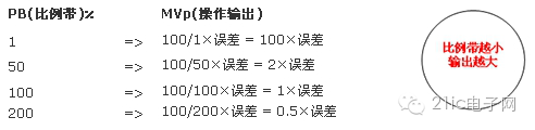
Figure 1

Figure 2: Relationship Between Proportional Band and Output
Steady-State Error (Offset)
In proportional control, an offset occurs when the system stabilizes at a non-zero error after some time. This happens because the proportional controller cannot completely eliminate the deviation between the setpoint and the actual value. The size of the offset depends on factors such as load changes and the system’s inherent characteristics. The mismatch between the load curve and the control curve is the main cause of this steady-state error. Unlike the proportional band, which does not produce offset, the system requires additional adjustments. One common method to reduce this error is through manual reset.

Figure 3: Offset Caused by Proportional Control
Manual Reset

Equation 1: MR – Manual Reset Value
As previously mentioned, pure proportional control cannot eliminate steady-state errors. To address this, the manual reset value (MR) can be adjusted to compensate for the offset. By manually setting the MR, the controller output can be fine-tuned to match the desired setpoint. Although this method works, it is not practical in real-time automatic control systems, where frequent manual adjustments are impractical. Therefore, the integral control function, which automatically adjusts the output based on accumulated error, is typically used instead.

Figure 4
Integral Control
Integral Control Action
Integral control (I) is designed to automatically adjust the controller output in response to any remaining steady-state error. It works by accumulating the error over time and gradually adjusting the output until the error is eliminated. This ensures that the system eventually reaches the setpoint. The rate at which the output changes is determined by the integral time. As long as an error exists, the integral action continues to adjust the output, making it essential for eliminating offsets.

Figure 5
Definition of Integration Time
The integration time represents the amount of time it takes for the integral action to produce the same effect as the proportional action. In other words, it measures how quickly the integral term responds compared to the proportional term. A shorter integration time means faster correction of the error, while a longer time results in slower but more stable adjustment.
Differential Control
Differential Control Action (D)
The differential control (D) function predicts future changes in the error signal by analyzing its rate of change. This allows the controller to respond proactively, improving stability and reducing overshoot. It is especially useful in counteracting the oscillatory behavior that can arise from integral control. By anticipating changes, differential control helps maintain a smoother and more responsive system.

Figure 6
Definition of Derivative Time
The derivative time defines how quickly the differential action responds to changes in the error. Specifically, it indicates the time required for the differential term to have the same impact on the controller output as the proportional term. A higher derivative time means the controller will react more aggressively to changes in the error signal, which can improve system responsiveness but may also introduce instability if not properly tuned.
Window Optical Lenses,Optical Lenses,Window Optical Lens,Calcium Fluoride Glass Window
Danyang Horse Optical Co., Ltd , https://www.dyhorseoptical.com