My amplifier works abnormally when channel multiplexing. What could be the reason?
Some people (especially engineers) claim that one way to question whether the debate is overspeed is to ask for a calibration certificate for the radar device. They believe that if the verification certificate expires, the driver should not be fined. Whether or not this is really suitable for everyone (the instrument may have been calibrated in the near future), the safest way to avoid speeding tickets is not to exceed the speed limit. But what if you don't realize that you are too fast? This reason usually doesn't work.
The same thing happens on the amplifier. In some applications, engineers may forget that the amplifier inputs are connected to devices with ultra-fast transients. For example, the multiplexer is buffered by the voltage follower (or instrumentation amplifier) ​​shown in FIG. The input signal is static and filtered by the RC network, reducing noise bandwidth or RF interference. The amplifier must be fast enough to be established between conversions, so the slew rate and bandwidth must be considered when selecting. However, in the lab, the results were not as expected: the amplifier output moved slowly, and the waveform was abnormal, creating a long tail. The setup time is far less than the specifications. Where is the problem?
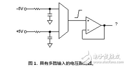
Many things can go wrong, but the fundamental problem is that the amplifier input is overloaded during channel switching. If the output moves at a slower speed than the input (or at least it does not move before the input moves), then a large differential voltage will appear between the two inputs. This condition can saturate the input transistor, increase the input bias current, positively bias the internal protection diode, or cause other unexpected effects. The actual response of such channel switching depends on the input topology, process technology, and internal protection circuitry, and also on the transient speed and voltage difference between adjacent channels. In addition to the amplifier's response to overload conditions, the increased input bias current (even if it flows only in the parasitic capacitance between the multiplexer and the op amp) charges or discharges the capacitance at the multiplexer input. . This interference changes the original level and can only be recovered by connecting the resistance between the source and the capacitor. If the time constant of the filter is large, a long tail length will occur at the output of the amplifier.
Depending on the source of the problem, there are a few things you can do to remedy the problem. In this case, the low-cost solution is to add a series resistor at each input connected to the fast source (multiplexer). This helps to avoid saturating the input by increasing the impedance of the source during transients. In the DAC output, or if the amplifier is used to condition a square wave from a microprocessor or FPGA, a simple RC helps reduce the edge speed and thus the amplifier operates normally. Specific situations require specific analysis to determine the best solution, but please pay attention to transient conditions. And remember, the best way to stay away from trouble is to slow down!
Pcb Push Wire Connectors,Multipolar Wire Connectors,Board Connector,Smd Connector
Jiangmen Krealux Electrical Appliances CO,.Ltd , https://www.krealux-online.com