introduction
This article refers to the address: http://
With abundant reserves, less exhaust pollution and good economy, natural gas has gradually become a good alternative fuel for automobiles. In the case of dual-fuel vehicle modification, the original engine structure is generally not changed in order to balance the performance when using gasoline [1]. Because the combustion characteristics of gaseous fuel and gasoline are different, the original ignition system cannot fully exert the performance of gaseous fuel, and the power is obviously reduced. . In [2], the ignition advance angle controller is designed for the high octane number of gas fuel and the slow propagation speed of gas fuel flame, and good results are obtained. However, different models of engines, the MAP map of the ignition advance angle is different, and the acquisition of the MAP map requires a lot of experiments, a long development cycle, high cost, and limits the wide application of such ignition controllers. The dual-fuel vehicle ignition controller designed in this paper comprehensively controls the ignition advance angle and ignition energy, does not need to obtain the ignition MAP map, shortens the development cycle and cost, has strong versatility, and can significantly improve the vehicle's power and reduce emissions.
Ignition parameter control scheme design
The performance of the ignition system is mainly reflected in the ignition timing and ignition spark strength [3]. Due to the slow propagation speed of gaseous fuel combustion, long ignition delay period and high ignition temperature, the automobile needs a larger ignition advance angle and ignition energy than gasoline when burning natural gas. In this paper, the ignition advance angle is controlled by setting the adjustment switch on the controller to select different ignition adjustment angles according to the fuel used. The ignition angle can be adjusted from 0o to 20o for natural gas, liquefied petroleum gas, gasoline and other fuels. Be applicable.
For a six-cylinder engine, the ignition signal given by the Hall sensor on the distributor corresponds to a crankshaft rotation of 120o (180o for four cylinders). If the time corresponding to the ignition signal output of the scoring appliance is T, the crankshaft turns to 1o. The time is T/120. If the ignition advances ao in advance, the phase shift in the time domain is Dt=(ao/120o)*T, where T is the amount that can be measured, and ao is the advance angle set by the dial switch. The adjustment range is 0-20o. When ao=20o, Dt/T=1/6; when ao=10o, Dt/T=1/12; when ao=0o, Dt/T=0; as long as the proportional relationship between Dt and T is determined, It is possible to make the ignition advance angle change with the ignition frequency to a certain value. In order to make the angle adjustment more precise, 16 gear positions are set by the dial switch to select the advance angle, that is, the advance angle. ![]() Where x is the code value corresponding to the dial switch,
Where x is the code value corresponding to the dial switch, ![]() The value is taken into Dt=(ao/120o)*T,
The value is taken into Dt=(ao/120o)*T,  That is, 1 unit x corresponds to an ignition advance angle of about 0.67o.
The amount of ignition energy is related to the primary current of the ignition coil. The primary current is controlled by the primary loop conduction time, so an optimal conduction time is controlled. The conduction time of the primary circuit of the traditional ignition system is limited by the shape of the cam or the signal of the sensor. Due to the constant duty cycle, the engine is running at a low speed, the primary circuit has a long conduction time, the primary current is large, and the ignition coil is prone to heat; The primary circuit has a short on-time, a small primary current, a low secondary voltage, and an unreliable ignition [4]. In this paper, the ignition conduction time is controlled by a single-chip microcomputer, and the setting of the duty ratio can be changed with the change of the frequency. The charging time of the ignition coil is generally saturated at 10ms, so when the ignition signal frequency is low, the charging time is guaranteed to be 10ms; when the ignition signal frequency is increased, the ignition period is less than 10ms, the discharge time of 2ms is reserved, and the rest of the time is fully turned on, fully The duty cycle of the ignition signal is utilized to ensure optimum on-time when the engine is running at high speed and low speed.
Ignition controller hardware design
The hardware component block diagram of the ignition controller with the single chip as the core is shown in Figure 1.

The shaping circuit shapes the signal output by the distributor to make it a pulse signal that can be processed by the single chip microcomputer, and the signal is applied to the I/O port of the PIC microcontroller through the photoelectric isolation circuit. The one-chip computer adopts Microchip's PIC16F73 single-chip microcomputer. This type of single-chip microcomputer has the advantages of high running speed, low power consumption, strong driving ability and abundant peripheral modules [5]. This system mainly uses the timer module, external interrupt module and output comparison of single-chip microcomputer. Module. The single chip processes the input signal, and then controls the conduction and cutoff of the high power tube in the power drive circuit through photoelectric isolation to realize the control of the ignition advance time and the ignition closing time. In the drive circuit, the output signal is first amplified by a three-stage tube, and then the high-power FET is controlled to be turned on and off, and the output peak current can reach 8-9A (the original car is 6-7A).
Since the voltage provided by the car is DC 12V, and the MCU needs 5V DC voltage, the corresponding power supply circuit is designed. The three-terminal voltage regulator 78M05 converts 12V into 5V, which supplies power to the MCU and other parts of the circuit.
Four dial switches are set on the controller, representing 2, 4, 8, and 16, respectively. The adjustment of the ignition advance angle can be achieved by different coding combinations. The controller draws 5 lines for connection with the car, which are 12V power line, ground line, distributor signal input line, controller signal output line, and distributor power line.
Ignition controller software design
The input signal frequency range of the single-chip microcomputer is 0-200Hz, the duty ratio is generally 2:3, the falling edge of the input signal is the ignition timing point, and the pulse width is the ignition coil charging time. The MCU program completes the advancement of the ignition timing and the adjustment of the duty cycle.
The system main program and external interrupt program flow chart are shown in Figure 2 (a), (d). The MCU first completes the initialization of the timer, external interrupt, CCP1 and CCP2 compare interrupts, uses the external interrupt to detect the time interval between two adjacent falling edges, and stores and clears the TMR1 value in the external interrupt service routine. The stored value is Cycle T.
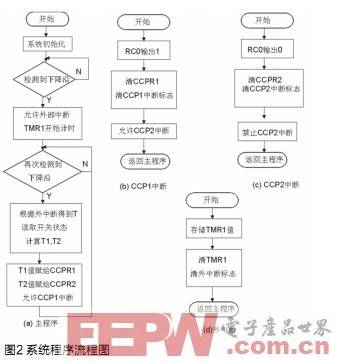
When T≥12ms, the car runs at medium speed and low speed, the ignition signal can meet the charging time of 10ms and the discharge time of 2ms, and the value of T-10ms-Dt is stored in the CCPR1 register; when T<12ms, the ignition signal When the charging time of 12ms and the discharge time of 2ms are not satisfied, the 2ms discharge time is guaranteed, and the rest of the time is all turned on, and the value of 2ms-Dt is stored in the CCPR1 register.
When T≥50ms, the car is in the starting state, and the operating condition is unstable. In this case, the ignition advance angle maintains the angle of the original car; when T<50ms, the car is in normal operating condition, and the MCU detects the external switch. The signal determines the falling edge of the output signal (where x is the read switch value) based on the calculated spark advance angle, and stores the value of T2=T-Dt in the CCPR2 register.
The CCP1, CCP2 interrupt program flow chart is shown in Figure 2 (b), (c). When the value in TMR1 is equal to the value in CCPR1, it enters the CCP1 interrupt service routine, the RC0 pin outputs a high level, and turns on the CCP2 interrupt. When the value in TMR1 is equal to the value in CCPR2, it enters the CCP2 interrupt service routine, and the RC0 pin outputs a low level. The ignition pulse signal is output by the cooperation of CCP1 and CCP2 to realize the adjustment of the ignition advance angle and the ignition duty ratio.
Ignition controller simulation test results analysis
The ignition controller designed in this paper is simulated on the automobile ignition test bench. The input/output waveform comparison of the engine under different rotation speeds and ignition advance angle is measured by the oscilloscope as shown in Fig. 3 and Fig. 4.
Figure 3 shows the input signal frequency when the input signal frequency is 50Hz and the dial switch code is x=20. It can be seen from the figure that the falling edge of the output signal is about 2.2ms earlier than the input signal, according to the formula Dt=(ao/ 120o)*T is converted to an angle of 13.2o; the pulse width is 10ms, which is 3ms less than the input signal. Since the ignition coil primary circuit is turned on for 10ms, it is saturated. If the time is too long, the coil will be damaged, so the on-time is low at low speed. Intercept.
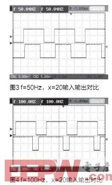
Figure 4 shows the comparison of the input/output waveforms when the input signal frequency is 100 Hz and the DIP switch is coded as x=20. It can be seen from the figure that the falling edge of the output signal is about 1.1ms earlier than the input signal, and the angle is 13.2o, the pulse width is 8ms, which is about 1.5ms longer than the input signal, which increases the conduction time of the primary current and improves the ignition energy. .
After waveform comparison analysis, it can be seen that the on-time is intercepted at low speed to reduce the damage to the ignition coil; the utilization of the duty ratio is optimized at high speed to ensure the ignition energy, and the ignition advance angle can be performed by the coding switch. Set to meet system design requirements.
Ignition controller bench test results
The ignition controller designed in this paper can be tested and tested by the automobile engine bench to significantly improve the economic performance of multi-fuel vehicles and reduce exhaust emissions. The CA6102 gasoline engine uses natural gas as fuel. The external characteristic test curve and load characteristic curve of the controller are shown in Fig. 5 and Fig. 6.
n=1800r/min
As can be seen from Figure 5, after the CA6102 gasoline engine is installed with natural gas as the fuel, the external characteristic power increases, increasing 1.4 kW at 1800 r/min, which is 2.7%, and the effective fuel consumption is reduced by 4.1% on average; at 2800 r/ The increase of 1.8kW at min was 2.8%; the effective fuel consumption decreased by 3.7%; as can be seen from Figure 6, the effective fuel consumption rate on the 1800r/min load characteristic decreased by an average of 4.3%.
The test data of the idle pollutants before and after installation are shown in Table 1. From the first table, it can be seen that the CO emissions are reduced by 30.5% and the CH compound emissions are reduced by 47.8%.
in conclusion
The dual-fuel vehicle high-energy ignition controller designed in this paper comprehensively controls the ignition advance angle and the ignition energy. It only needs to be connected to the controller in the original vehicle distributor and ignition coil to work. It can be used according to the fuel used. The setting of the ignition advance angle by the dial switch has the advantages of convenient use, strong versatility and low cost, and is of great significance for promoting dual-fuel vehicles, saving energy and environmental protection in China.
Fiber Patch Cord is a length of optical cable with connectors fixed on two ends to realize the optical path active connection.If both sides of the connector or its end-face are different, it is called hybrid Fiber Optic Patch Cables.Main types of Optical Patch Cord are SC Patch Cord , LC Patch Cord , FC Patch Cord , ST Patch Cord , Multimode Fiber Patch Cord,Single Mode Fiber Patch Cord, Duplex Patch Cord , Simplex Patch Cord . In order to assure of high performance,they are made with CCTC brand`s premium grade connectors.Meanwhile,Fiber Optic Patch Cord is also available with different colors,diameter and jacket types, which can be made to any length to fit FTTH projects. Fiber Patch Cables are not only widely used for communication rooms,FTTH,LAN,fiber communication systems,fiber optic transmission equipment and other telecom fields,but also they are applicable to cable television networks, telecommunications networks, computer optical network and optical test equipment. Foclink,a reliable supplier of fiber patch cord is always beside u 7*24.
Fiber Patch Cord
Fiber Optic Patch Cord,Optical Patch Cord,Fiber Patch Cables,Fiber Optic Patch Cables
Foclink Co., Ltd , http://www.scfiberpigtail.com