one. Preface With the wide application of programmable controllers (plc) in the field of industrial control, plc programming has become a professional skill that electrical engineering technicians must master. There are many brands of programmable controllers, and PLCs in Europe, America, Japan, Korea and Taiwan have rushed to the mainland, providing users with a variety of choices, but also bringing a little trouble to users. Since the programming cables of different brands of PLCs are not universal, buying an original cable is often thousands of dollars. For those who use learning as their main purpose and often encounter different brands of PLCs, it would be convenient for them to have a programming cable at a lower cost. Although PLC has many brands, the programming interface of various brands of PLC is no more than several types. In the technical manual provided by PLC, the pin definition of programming port is also provided, which provides the possibility of self-made programming line. Below I will explain how to DIY a suitable programming cable for several serial communication interface standards and physical structures of the PLC programming port.
two. One end of the type programming cable of the PLC programming port is connected with the COM port of the PC, the other end is connected with the programming port of the PLC, and the COM port of the PC end is RS232C interface, DB-9 pin plug. The PLC programming port can be generally divided into three types according to the interface standard, namely RS232, RS485, RS422. According to the physical structure, it can be divided into five types, namely eight-pin round mouth (DIN-8), nine-pin D-shaped port (DB-9), twenty-five-pin D-shaped port (DB-25), RJ11 port and special interface. The former two are mostly, and the interface pins are arranged as shown in Figure 1. 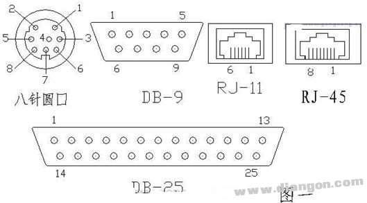
In order to make programming cables, we must first understand the three serial communication interface standards. RS-232, RS-422 and RS-485 are three serial data interface standards. The interface standard only specifies the electrical characteristics of the interface, and does not involve connectors, cables or protocols. Therefore, the same interface standard can have Different physical structures, such as DB-9, DB-25, etc. RS-232 is the most widely used serial interface in the PC and communications industries. The RS-232C bus standard has 25 signal lines, including a main channel and an auxiliary channel. In most cases, only the main channel is used, and nine signal lines (nine-pin D-shaped ports) are commonly used. The definition of each pin is shown in Table 1. For general duplex communication, only a few signal lines are needed. For example, the transmit data line TXD and the receive data line RXD and the logic ground line GND, the RS232C can only communicate point-to-point, the transmission distance is short, and the common mode rejection capability is poor. RS-485 uses balanced transmit and differential receive, so it has the ability to reject common-mode interference. It uses a pair of twisted pairs, one of which is defined as A (TXD-/RXD-) and the other is defined as B (TXD+/RXD+), which does not require a digital ground. The communication distance is above 1200 meters when the rate is 100kbps or less. RS-485 can be networked to form a distributed system that allows up to 32 drives and 32 receivers to be connected in parallel. RS-485 can only implement half-duplex communication.
Table 1: RS-232 interface pin definition
25-pin 9-pin abbreviated description
2 3 TXD send data
3 2 RXD receiving data
4 7 RTS request to send
5 8 CTS is allowed to send
6 6 DSR communication equipment is ready
7 5 GND Signal Ground
8 1 CD carrier detection
20 4 DTR data terminal is ready
22 9 RI ring indicator
The RS-422 interface standard is mainly established to overcome the short communication distance and slow transmission rate of the RS-232 interface standard. The RS-422 standard is a standard transmission in a balanced manner. Two pairs of twisted pairs are used. Each signal is transmitted by two signal lines, that is, transmit data TXD+, TXD-, receive data RXD+, RXD-, logic level. It is determined by the potential difference between the two transmission lines. Due to the use of two-wire transmission, the ability to resist common mode interference is greatly enhanced, so the maximum data rate can reach 10MbPs (15m transmission). If the transmission rate drops to 90kbPs, the maximum distance can reach 1200m, which can realize full-duplex communication.
three. PLC programming cable production The function of the programming cable of each manufacturer is to convert the RS485 and RS422 format data of the PLC end into the RS232C format data of the PC end. If the PLC end is RS232, it can be directly connected according to the rules. Therefore, to make the PLC programming cable, you must convert the RS485 and RS422 of the PLC end to the RS232C that the PC can recognize. The PC can communicate with the PLC to complete the downloading, uploading, monitoring, etc. This involves an interface standard conversion problem. There are several ways to implement interface conversion: First, use a simple level conversion circuit, but a circuit can only be used for one type of PLC, and the function is not complete, the performance is not reliable, and may even damage the serial port of the PC; Converting the IC with a dedicated interface, but the amateur implementation is more complicated and not suitable for self-made. Here we use a finished communication interface converter, which can realize RS232/RS485/RS422 conversion. (http://) Because it is a dedicated communication interface converter, it is very convenient to use and performance. Reliable and low price.
There are many products in this market. Take the SC-485C interface converter of Sichuan Deyang Four Star Electronics as an example. The converter is used for RS232 to RS485/RS422 communication conversion. It is small in size and only has two DB-9 plug sizes. Serial port stealing technology is used, no external power supply is required. The structure and pin definition of SC-485C are shown in Figure 2. The RS232 end is the DB-9 socket, which can be directly inserted into the COM port of the PC. The RS485/RS422 terminal is the DB-9 socket. When RS485 is used, the 3 pin and the 8 pin. When the RS422 is used, the 3 pin and the 8 pin. 1 foot and 7 feet. Using the interface converter to make the programming cable is shown in Figure 3. The left side is the SC-485C interface converter, and the right side is the programming cable of DIN-8, RJ11, DB-9 and DB25 plugs from top to bottom. The plugs on the side of the cable near the interface converter are DB-9 hole plugs. The other end is a pin plug, which corresponds to the PLC programming port of different physical structure. 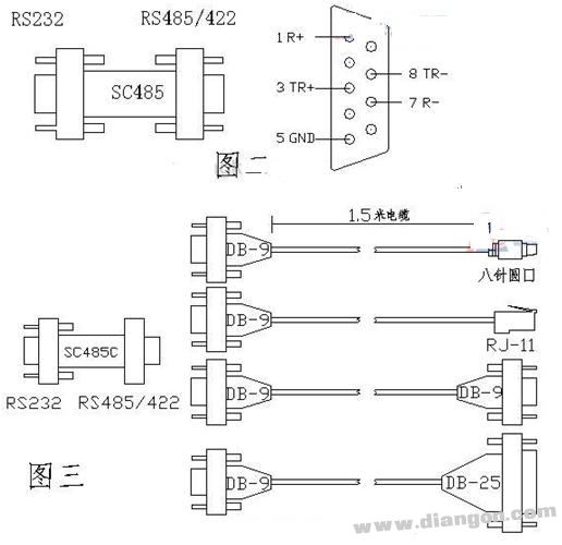
According to the PLC side, RS485 or RS422 is selected according to the PLC terminal. According to the rules of “send and receive, receive and send, positive, negative and negativeâ€, the connection diagram of SC-485C interface converter and PLC RS485 and RS422 interface Connect with PC and PLC RS232 interface as shown in Figure 4.
Figure 4 
To do a programming cable, in addition to the interface conversion between RS232/RS485/RS422, you must also understand the definition of each pin of the PLC programming port, because even the same interface standard, the PLC of different manufacturers The foot distribution is also different. Table 2 provides pin definitions for several mainstream PLCs for reference. Unlisted PLCs can be searched for random technical manuals, or you can find a general human-machine interface (hmi) manual on the Internet. You can find the most PLCs on the market in the connection description between HMI and PLCs. Foot definition.
Table 2 part of the PLC programming port pin definition
PLC model interface standard interface profile pin definition
S7-200 RS485 DB-9 3B/8A
TIWDO/NEZA RS485 DIN-8 1A/2B
LGmasterK Series RS232 DB-9 2RXD/3TXD/5GND
FX2N/FX0N RS422 DIN-8 1RXD-/2RXD+/4TXD-/7TXD+
OMRON CH200HS RS232 DB-9 2TXD/3RXD/7GND/4RTS/5CTS
AB SLC503/504 RS232 3TXD/2RXD/5GND/7RTS/8CTS
ABB COMLI RS232 6TXD/ 7RXD/ 5GND
(SLAVE MODE)
KOYO DIRECT DL RS232 RJ11 4TXD/3RXD/1GND
Fourth, the conclusion that an original cable can only be used on a PLC, and an interface converter with different connectors can be combined into a set of programming cables, which can be used on almost any brand of PLC. Interface converters and connectors are available in the communications market, and are inexpensive, with a total cost of only about one-tenth the price of the original cable, making it very easy to manufacture. The self-made programming cable can complete the functions of program uploading, downloading and online monitoring between the PC and the PLC. It can be said that the function and reliability are comparable to the original cable.
RS232 to RS485 homemade line schematic 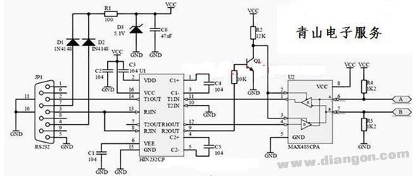
Production of Serial Communication Cables For the production of RS-232 communication cables, whether it is a 9-hole plug or a 25-hole plug, the serial communication cable must be connected to the following docking relationship:
SGâ†â†’SG TXDâ†â†’RXD RXDâ†â†’TXD RTSâ†â†’CTS
CTSâ†â†’RTS DTRâ†â†’DSR DSRâ†â†’DTR
According to the above docking relationship, the serial communication cable can be connected very conveniently. Here, by the way, the meaning of the above pins is represented:
SG English is called Signal Ground/Common Return, which means signal ground;
TXD refers to Transmitted Data, indicating data transmission;
RXD refers to Received Data, indicating receiving data;
RTS refers to Request To Send, indicating that the request is sent;
CTS refers to Clear To Send, indicating a clear request;
DTR refers to Data Terminal Ready, indicating that the data terminal is ready;
DSR refers to the Data Signal Rate Selector, indicating that the data is set ready.
When making a 9-pin serial cable, you need two 9-pin plugs and a 1.5-meter long flat cable of at least 7-pin. The pin connections are as follows.
The 9-hole plug--9-pin plug pin connection is: 2-3, 3-2, 4-6, 5-5, 6-4, 7-8, 8-7.
The 9-hole plug -25-hole plug pin connection is: 2-2, 3-3, 4-6, 5-7, 6-20, 7-5, 8-4.
The 25-pin plug -25-hole plug pin connection is: 2-3, 3-2, 4-5, 5-4, 6-20, 7-7, 20-6.
Delta's DOP series touch screen is connected with various brands PLC communication
1. GE VERMAX programming cable production (the first serial port of the power module):
PLC PC
(9 SUB MALE) (9 SUB FEMALE)
2 (T) 2 (R)
3 (R) 3 (T)
5 (G) 5 (G)
2, GE 90-30 series (CPU351/352/363/364) programming cable production (RS232 port 6 pin RJ11 type):
PLC PC
(6 RJ11 MALE) (9 SUB FEMALE)
2 (T) 2 (R)
5 (R) 3 (T)
3 (G) 5 (G)
3, GE 90-30, 90-70, VersaMax programming cable production (RS232 port 6 pin RJ11 type):
PLC RS422/RSRS232 PC
(15 SUB MALE) (9 SUB FEMALE)
12 (T-) (R+) (T) 2 (R)
13 (T+) (R-) (R) 3 (T)
10 (R-) (T+) (G) 5 (G)
11 (T+) (T-)
9 (RT)
6 (RTS-)
15 (CTS-)
6 (RTS+)
15 (CTS+)
4. The programming cables (GE 90-30, 90-70, VersaMax) produced by GE are not long enough in the debugging process, and need to be extended. The extension line is made the same.
Note that the GE 90-70 has two 15 SUB FEMALE serial ports that can be programmed with a second serial port, using GE's programming cable.
OMRON CPM1A programming cable production information, (Figure) 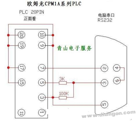
Second, Omron plc programming cable

Siemens s7-200 and 300 programming cable manufacturing method 

Siemens s7-200 and 300 programming cable manufacturing method
| 2010-06-19 21:34:17 4th floor
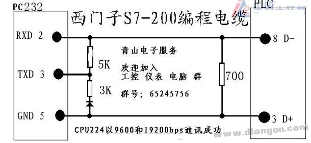
S7-200: PPI communication method
1: Programming cable with siemens PPI
2: With rs232/485 converter, the connection mode of 485 and plc PPI port is: 3-Data+ 8-Data-s7-300, 400: through MPI communication, using siemens adapter (PC-Adapter), one end of the adapter Directly connected to the MPI port of the plc, the other end of the adapter uses the following connection. 1-1 2-3 //Send 3-2 //Receiver 4-6 //Send acknowledgment 5-5 //Common 6-4 //Receive acknowledgment 7-8 //Send complete 8-7 // Accept completed 9-9 Profibus:
1: Use a dedicated cable, usually A1-A1 B1-B1
2: Make 3-3 8-8 yourself
Production of s7200 and TP170B communication cable
3--3; 8--8.
Schneider programming cable production. 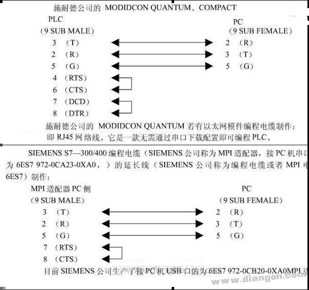
WEINVIEW touch screen programming cable production: touch screen WeinView/EasyView programming cable production method
Production of Mitsubishi FX series PLC programming cable for Mitsubishi FX1S, FX1N, FX2N, FX2NC and A series PLC programming.
The first step: make a FX-422CABO. 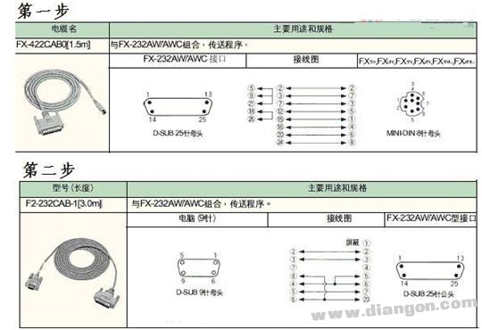
Step 2: Make a F2-232CAB-1
Step 3: Dock the 25-pin female connector with the two wires and the male plug.
The above picture is actually the serial port of the computer directly corresponds to the DIN8 hole of the PLC;
Computer PLC
twenty two
3 7
5 3
6 and 8 shorted 6
Well, a Mitsubishi plc programming cable SC-09 was completed.
Mitsubishi FX series programming cable Mitsubishi PLC programming cable production materials

Production of computer and PLC/CQM1H series programming cable XW2Z-200S-CV
PLC-PC: 2-2 3-3 4-8 5-7 9-5
The LG PLC programming cable manufacturing method is made using RS232 serial port and shielded cable.
Male 2 (white) <-----> mother 3 (white),
Gong 3 (Yellow) <----->Female 2 (Yellow)
Male 5 (red) "-----" mother 5 (red),
The shield is sheathed and welded to the metal casing.
The above colors are custom. If the wire diameter is too thin, the interface card is not strong. You can fix it with an electrical tape and thicken it before installing the interface cover.
Fuji PLC programming cable production method is as follows:
1. Directly connected programming cable, the production method was originally referred to Mitsubishi PLC programming cable production method. At the beginning, there was no method for making Fuji PLC programming cable on the Internet. In the touch screen programming manual, Fuji PLC was used to RS422 communication, and the communication port was downloaded as shown in the figure. I started to prepare with RS232/422 converter, but I didn't buy it locally. Think of Mitsubishi PLC is also RS422 communication, a lot of Mitsubishi programming cable production map online, downloaded a Mitsubishi wiring diagram and made a Fuji programming cable.
The programming cable made with resistors has a very low chance of success with V1.0 Chinese version Fuji software, about 10%. In the workshop, the success rate of notebooks is 0, and Zhengzhou purchases RS232/422 module to make another programming cable. Who knows that the programming cable made by converter has a chance of success in the office, 0, not to mention the workshop. Always use the resistor-connected programming cable and remove the PLC into the office input program and install it on the shop floor. Until later, a good-hearted industrial control friend said that the V1.0 Chinese version of the software is online WIN98 system software, XP system must use V2.0 and later versions. Download and install the V2.0 version of the software, the programming cable made by the two methods can be used.
[attach]42[/attach]
4 RTX+ -------------------------5 GND
6 TXD+ -------------------------5 GND
3 RXD— ------2.2K resistance ------3 RXD
5 TXD — ------2.2K resistance ------2 TXD
Connect the wire of the 4 (RXD+).6 (TXD+) pin of the PLC to the 5 pin of the 9-pin female of the computer (this pin is the ground of RS232).
The 3 pin (RXD-) is connected to the 9-pin 3 pin through a 2.2k ohm resistor.
Pin 5 (TXD-) is connected to the 9-pin 2 pin via a 2.2k ohm resistor
2. Connect RS232-422 converter head to the computer market to purchase an RS232-422 converter head (about 25 yuan, safer than the resistor connection), according to the instructions of the converter head and 8 core crystal head according to RTX+ connected RTX+; RTX- Connect RTX-; TXD+ connect TXD+; TXD- connect TXD- connect.
After a friend's online connection was unsuccessful, I concluded that they did not succeed because of the following reasons:
1 If there is a USB/RS232 converter, note that the converter must be powered separately. If the converter can be powered from +5V, you can use the +5V power supply of the PLC directly. If the converter is powered by +9V, it may be necessary to add another DC power supply;
2 software must use 2.0 English version, 1.0 Chinese version can be used in the following programming, 1.0 is available in WIN98 system, the success rate in XP system is not high (accidentally can be successful once).
3 Determine whether the wiring is correct, you can insert the crystal head into the PLC programming port (PLC NB2 has a port is not a programming port, do not insert the wrong) to measure whether +5V is 1/7 and 2/8 feet. Several friends have mistaken the crystal head up and down the program. Several friends have reversed the order of communication ports 1~8. After plugging in the PLC communication port, measure the polarity of 1 pin and 2 pin + 5V to judge whether it is wrong.
Fuji spb plc programming cable internal wiring diagram!
One end 8-core crystal head one end rs232 9 holes
RJ45 end 3-----TD+; 4-----TD- ; 5-----RD+ ; 6-----RD- ; 1,2,7,8---NC
SPB is in RS422 mode, so at the end you need an RS232 to RS422 converter ~ ~ and then the pin distribution on the converter.
A lower version of the software will cause the communication to fail. Please use a higher version of the software.
F930GOT-BWD-C programming cable
PC HMI
2--------3
3--------2
4--------6.8
5--------5
6.8-----4
4400 and OMRON CP1H communication cable production
Plc-----------hmi
3 3
twenty two
9 5
4,5 short homemade Panasonic PLC (FP0) programming cable diagram 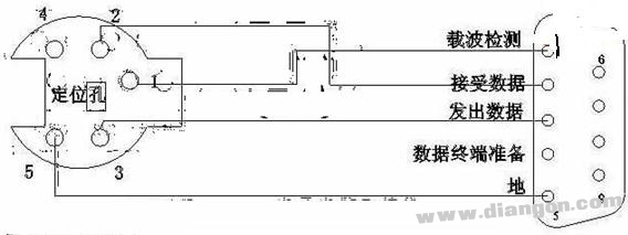
The present invention provides a method for controlling the temperature of a flue-cured electronic cigarette and a flue-cured electronic cigarette. The flue-cured electronic cigarette includes an N-section heating body, where N is an integer greater than 1, and the heating body is used for heating tobacco. The method for controlling the temperature of the flue-cured electronic cigarette includes: the flue-cured electronic cigarette heats the i-th heating body, and i is an integer greater than 0 and less than N; after the first preset time, the flue-cured electronic cigarette pairs the i+ The first stage heating body is heated; after the second preset time, the flue-cured electronic cigarette stops heating the i-th stage heating body, and continues to heat the i+1th stage heating body. The technical solution solves the problem of unbalanced smoke output of flue-cured electronic cigarettes during multi-stage heating.The present invention provides a method for controlling the temperature of a flue-cured electronic cigarette and a flue-cured electronic cigarette. The flue-cured electronic cigarette includes an N-section heating body, where N is an integer greater than 1, and the heating body is used for heating tobacco. The method for controlling the temperature of the flue-cured electronic cigarette includes: the flue-cured electronic cigarette heats the i-th heating body, and i is an integer greater than 0 and less than N; after the first preset time, the flue-cured electronic cigarette pairs the i+ The first stage heating body is heated; after the second preset time, the flue-cured electronic cigarette stops heating the i-th stage heating body, and continues to heat the i+1th stage heating body. The technical solution solves the problem of unbalanced smoke output of flue-cured electronic cigarettes during multi-stage heating.
E-Cigarette Starter Kits,small e cigarette starter kit,mini e cigarette starter kit,e cig starter kit near me,cheapest e cigarette starter kit, e cigarette starter kits,electronic cigarette starter kits
Suizhou simi intelligent technology development co., LTD , https://www.msmvape.com