RFID technology has made great progress in recent years. The widely used frequency bands are distributed in the LF, HF, UHF and Huibo frequency bands. The RFID systems in each frequency band have their own advantages and corresponding application scope. For the RFID system of the LF band, the most obvious advantage is that it has good penetrating properties, such as liquid-permeable substances, buildings, human bodies, etc., and various animal somatic cells and various gas molecules on the LF band. Energy absorption is small.
It can be seen that the LF RFID system works well in applications that require good penetration, require uninterrupted long hours of operation, and have high risk conditions, such as explosive gas mines. This paper proposes a STM32-based LF RFID system because of its important advantages, and designed and tested the system. The test results show that the system has the characteristics of simple implementation and high reliability.
According to the principle of RFID system, the LF system generally consists of the following three parts:
1) Electronic label: It should be placed on the object to be identified. In this design study, the standard 125 kHz electronic label EM4100 in industrial production is mainly used. Its built-in small ROM and rectifier circuit enable contactless operation of the transponder and reader.
2) Reader: It can be a read or write/read device, depending on the structure and technology used, mainly to read the label.
3) Antenna: The antenna should be placed between the transponder and the reader. It mainly serves as a bridge for communication. Whether it is energy supply or information transmission, it must be realized by coupling components.
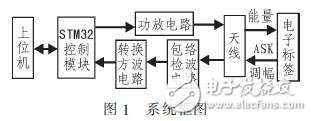
1 overall system design
This design uses STM32 as the core of the control module. It provides a driving signal for the rear power amplifier circuit by outputting a square wave source of 125 kHz. The power amplifier circuit provides an amplified 125 kHz square wave for the antenna load, so that the antenna load can provide the label. Enough energy while getting tag information. The detection circuit realizes the detection function of the tag information. After detection, it is converted and transmitted to the STM32 for decoding by the square wave signal conversion circuit, and the tag information is transmitted to the host computer through the STM32 serial port for subsequent processing. The entire system block diagram is shown in Figure 1.
The difference between this system and the existing system is:
1) No dedicated decoding chip is required for decoding. The detection-converted electronic tag signal is directly decoded by the capture function of the STM32.
2) The STM32 can be used to output a pair of dead square complementary square waves to drive a pair of switch tubes, eliminating the need for complex analog electronic circuits to generate the same drive waveform.
3) Learning from the principle of the half-bridge inverter circuit in the switching power supply, the IC circuit forms a series resonance, thereby realizing the power amplification.
2 hardware circuit design
2.1 power amplifier circuit design
The power amplifying circuit is formed by two switching tubes and an LC oscillating circuit (antenna), and the designed power amplifying circuit is designed as shown in FIG. 2 .
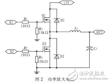
Among them, S1 and S2 are two PWM signals with dead zone control after the STM32 outputs the driven chip IR2110, and the frequency is 125 kHz. In this way, the antenna L1 and the capacitor C1 form a series resonant circuit with a resonant frequency of 125 kHz. The function of the resonant circuit is to obtain the maximum current of the antenna, thereby generating magnetic flux and obtaining a larger card reading distance.
The antenna itself is a low-resistance device. Connecting the antenna coil to the power amplifier circuit requires estimating the equivalent circuit and quality factor of the antenna to derive the recommended capacitance of the matching circuit.
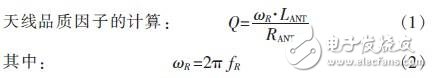
In general, due to the magnetic field radiation of the antenna, the Q value requirement is preferably between 20 and 40. Now based on the Q value of the antenna to determine the antenna's sensitivity, some current industry standards mainly use winding 50 Ω, Q value is 30, the working frequency is 125 kHz, fR takes 125 kHz, from the above 3, data can get RFID The antenna has a sensitivity of 375 μH.
Antenna winding: First, roughly a few turns, then use an impedance analyzer to measure the inductance at 125 kHz operating frequency. In this design, the inductance is 89.03 μH after 10 turns of detection. Inductance calculation formula:
L = N2 & TImes; L1 (3) (L1 represents a single-turn inductance, and N represents the number of turns of the coil). From the above formula, the single-turn inductance of the antenna can be found to be 0.89 μH. That is, the value of the above inductance can be used to determine the number of turns required for the antenna, which requires about 21 turns.
After the antenna design is completed, the corresponding impedance matching circuit needs to be selected. Now the design mainly chooses to use CBB capacitors to achieve impedance matching. The size of the capacitor is determined by the operating frequency of the system. The main purpose of impedance matching is to make the antenna work in an optimal state, that is, the antenna and the capacitor are in resonance.
Calculate the formula of the size of the capacitor from the above:
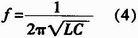
This formula determines that the capacitance is 4.7 μF. The withstand voltage of the CBB capacitor also needs to be determined based on the peak value of the oscillation waveform passing through the capacitor.
2. 2 design of envelope detection circuit
The design of the envelope circuit largely determines the reading distance of the RFID reader. Its main working principle is that the low-pass filter and the two-pole arm work in series to filter the high-frequency 125 kHz wave. The circuit design mainly uses series diode envelope detection, and its working principle is shown in Figure 3.
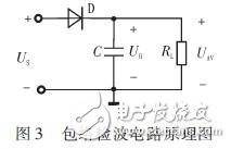
The circuit consists of a diode D and an RLC low pass filter connected in series. When Us is input, the current i through D produces an average voltage UAV in the RLC circuit, which in turn reacts to D (called the average voltage negative feedback effect), affecting the current through the diode.
If Us=Vcm(1+MacosΩt)cosωct, then vov=ηdVcm+ηdMaVcmcosΩ=VAV+Vov, where vovâˆvΩ, so linear detection is achieved.
LiFePO4 Automotive STARTING Battery
A class lithium Battery
Superior selection for materials & parts
Exquisite workmanship
High-quality handicraft grade look and workmanshipHigh class ABS container with abrasive coating
High class brass terminals make low internal resistance and strong discharge performance
Convenient installation in car
LiFePO4 Automotive Starting Batteries
Powersports Battery,Lithium Starting Battery,Lifepo4 Starting Battery,Lithium Automotive Battery
Starlight Power Industrial Company Limited , https://www.starlite-power.com