Abstract: This applicaTIon note is a guide for building software to control Remote Alarm generaTIon in all Dallas Semiconductor E1 Framers and Single Chip Transceivers (SCTs). The basis for Remote Alarm generaTIon is the European TelecommunicaTIons Standards Institute (ETSI) standard ETS 300-011 . ETS 300-011 is intended for systems which incorporate an Integrated Services Digital Network (ISDN), Primary rate user-network interface. The specification describes Layer 1 operation and test principles, which includes but is not limited to Remote Alarm generation. Remote Alarm generation is important because it is by the system for notification of a line fault. To ensure interoperability between many different E1 systems, it is important that each system follows the same specifications. This application note contains background information on ETS 300-011 and a complete software flow diagram, which illustrates how to properly generate a Remote Alarm in accordance with the specification.
Introduction to ETS 300-011The European Telecommunications Standards Institute, better known as ETSI, is a standards body that operates throughout the European Union. Their goal is to produce the telecommunications standards that will be used for decades to come throughout Europe and beyond. Further information on the ETSI organization can be found on their website at
The ETS 300-011 specification is intended for designs with an Integrated Services Digital Network (ISDN), Primary rate user-network interface. ETS 300-011 describes the Layer 1 specification and test principles for the ISDN interface. One aspect of the ISDN interface is the use of the Remote Alarm for notification of a line fault. This application note focuses on the use of the Remote Alarm and how to implement it in software.
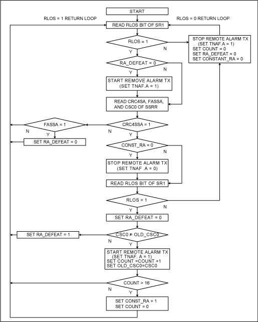
ETS 300-011 Software Loop DescriptionThe flowchart in Figure 1 can be used to implement the Remote Alarm functions in Dallas Semiconductor's singlechip transceivers or framers. It is based on the ETS 300-011 specification and designed to guide the software development.
Software Initialization SequenceThe following seven initialization tasks need to be performed prior to the flow chart sequence. Power Up All Necessary Hardware. Reset All SCT or Framer Registers to 0x00. Initialize All SCT or Framer Registers to Proper Values. Set Variable COUNT = 0. Set Variable OLD_CSC0 = 0. Set Variable RA_DEFEAT = 0. Set Variable CONST_RA = 0. Software FlowchartFigure 1 is the logical sequence that will implement the Remote Alarm functions of ETSI standard ETS 300-011.

Figure 1. Software flowchart.
Notes: The Remote Alarm is transmitted using the TNAF Register. When the A bit of the TNAF Register is set to 1, the Remote Alarm is being transmitted. The RLOS bit in the SR1 Registers is a latched status bit. To properly read the current status of the RLOS bit, the software should use a Write-Read-Write-Read sequence. The second Read will ensure the software obtains the current status of the RLOS bit.
Introduction to ETS 300-011The European Telecommunications Standards Institute, better known as ETSI, is a standards body that operates throughout the European Union. Their goal is to produce the telecommunications standards that will be used for decades to come throughout Europe and beyond. Further information on the ETSI organization can be found on their website at
The ETS 300-011 specification is intended for designs with an Integrated Services Digital Network (ISDN), Primary rate user-network interface. ETS 300-011 describes the Layer 1 specification and test principles for the ISDN interface. One aspect of the ISDN interface is the use of the Remote Alarm for notification of a line fault. This application note focuses on the use of the Remote Alarm and how to implement it in software.
ETS 300-011 Software Loop DescriptionThe flowchart in Figure 1 can be used to implement the Remote Alarm functions in Dallas Semiconductor's singlechip transceivers or framers. It is based on the ETS 300-011 specification and designed to guide the software development.
Software Initialization SequenceThe following seven initialization tasks need to be performed prior to the flow chart sequence. Power Up All Necessary Hardware. Reset All SCT or Framer Registers to 0x00. Initialize All SCT or Framer Registers to Proper Values. Set Variable COUNT = 0. Set Variable OLD_CSC0 = 0. Set Variable RA_DEFEAT = 0. Set Variable CONST_RA = 0. Software FlowchartFigure 1 is the logical sequence that will implement the Remote Alarm functions of ETSI standard ETS 300-011.

Figure 1. Software flowchart.
Notes: The Remote Alarm is transmitted using the TNAF Register. When the A bit of the TNAF Register is set to 1, the Remote Alarm is being transmitted. The RLOS bit in the SR1 Registers is a latched status bit. To properly read the current status of the RLOS bit, the software should use a Write-Read-Write-Read sequence. The second Read will ensure the software obtains the current status of the RLOS bit.
The Dry Type Transformers` materials are of high quality, scientific formula, and adopt advanced production testing equipment to produce according to strict process. The Dry Type Transformer has the characteristics of high reliability and long service life. Depending on the environment, different enclosures can be configured. It can be used as an upgraded product for Dry Transformer with low loss, low noise, obvious energy saving effect and free maintenance.
Dry Type Transformers
Dry Type Transformer,200 Kva Dry Type Transformer,50 Kva Dry Type Transformer,500 Kva Dry Transformer,Dry Type Transformers Manufacturers,Dry Distribution Transformers
FGI SCIENCE AND TECHNOLOGY CO., LTD , https://www.fgi-tech.com