The reference design provided in this article can increase the output current of the linear regulator MAX15006 / MAX15007 to meet the power supply requirements of automotive airbags.
With the increasing number of electronic devices in automobiles, a major challenge facing designers of electronic control modules is how to improve product performance under the premise of limited power budget. Today's cars include numerous electronic systems, such as: stereo and infotainment systems, wiper control, headlight drive systems, and airbags. These system requirements are dependent on car battery power, and designers must reduce the power consumption of each electronic system as much as possible, especially after the car is turned off and the car is parked in the parking lot.
After the car engine is turned off, the battery generally still needs to provide power for the operation of multiple systems. To reduce power consumption in this case, the power management module introduces several power-saving modes: turning off the microprocessor clock and turning off the converter circuit by enabling input. These are the two most common examples. However, some devices and functions—such as remote access control systems (PKE) and security systems—should always be kept in operation, regardless of whether the power source is from a generator or a battery. Figure 1 shows a typical airbag power module.
The reference design introduced in this article uses the MAX15006 / MAX15007 linear regulator to reduce the quiescent current of an automotive airbag. In addition to ultra-low quiescent current, these devices can also withstand load dumps up to 45V, making them ideal for harsh automotive working environments. In addition, they also have low dropout voltage, wide input voltage range, thermal protection and short circuit protection, enable input and other functions, which are ideal for automotive airbag power supply modules. 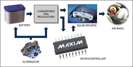
Figure 1. Typical automotive airbag power module
Since the diagnostic monitor always works, the power supply must have a very low quiescent current. In addition, in the event of a collision, the terminals of the AC motor may be disconnected from the battery terminal and a load dump may occur. In the automotive environment, even under normal operating conditions, a large battery voltage variation range may occur.
The MAX15006 / MAX15007 have several advantages—for example: ultra-low quiescent current, wide input voltage range, and load dump protection up to 45V—very suitable for power modules for automotive airbags. It can support most applications with a maximum current of 50mA without any external components. In some cases, the total current required by the airbag monitoring system exceeds 100 mA; when checking the ready state of the airbag opening device, the required current does not exceed 200 mA. Based on this consideration, we need to increase the output current of the MAX15006 / MAX15007, using an external regulator.
Increase the output current of the regulator. The minimum current when the airbag opening circuit works is 1.2A. The airbag start circuit is powered by a switching regulator (buck or boost converter) and a linear regulator. The power supply current required by the monitoring system (sensors, ADCs, start-up device ready detection, etc.) is approximately 150mA, which exceeds the power supply capability of the linear regulator (MAX15006 / MAX15007).
The external adjustment tube can expand the current driving capability of the linear regulator. In order to increase the output current of the linear regulator, connect the regulator tube between the input and output as shown in the figure below (Figure 2) ¹, this circuit increases the output current to 150mA.
Figure 2. This circuit adds an adjustment tube outside the MAX15007 to provide sufficient output current for the airbag monitoring system.
R1 selects 1Ω, R3 selects 2.2Ω resistor to ensure minimum power consumption. In addition, when the value of R1 is less than 1Ω, the heat consumption of the PNP transistor may increase. When starting work, there is no current output, and no current is passed through the external regulator. As the operating current gradually increases, it will produce a voltage drop of approximately 0.6V through the diode, causing the diode to start conducting. The turn-on voltage of the diode provides a sufficient voltage difference between the base and the emitter, so that the PNP transistor is also turned on, thereby providing the additional current required by the load. The role of R2 is to compensate for the higher dynamic resistance of the diode at low current settings. When the load current is less than 25mA, the external regulator tube is disconnected. Changing the resistance value can increase the supply current to the circuit.
Reasonably choose the output capacitor to ensure the stability of the system. Because the circuit is connected to an external transistor, the output voltage will be unstable when using the 2.2µF output capacitor specified in the data sheet, because the transistor increases the gM of the regulator, which will result in a unity gain bandwidth. Ascension, the reasons for ascension are:
Unity gain bandwidth ∠gM
In order to maintain the same unity-gain bandwidth as the steady state, the output capacitance needs to increase correspondingly according to the increase in gM. The increase in gM can be obtained by measuring the current gain of the additional circuit.
The current gain of the external circuit can be calculated with a small-signal approximation circuit (Figure 3).
Figure 3. The size of the output capacitor must be determined by calculating the current gain of the external circuit
Assume that ΔI is the amount of change in the load current of the regulator when there is no external adjustment tube. After connecting the external adjustment tube, the change in current flowing through the PNP adjustment tube is K ΔI. Therefore, due to the presence of the external adjustment tube, the total change in load current is ΔI + K ΔI, that is: (1 + K) ΔI. Therefore, gM is increased by (1 + K) times, then, in order to ensure the same unity gain bandwidth, the output capacitance should also be increased by (1 + K) times.
In our circuit, the value of K can be calculated by the following formula:

Considering the influence of parasitic effects, the required capacitance value is 5.45 times the minimum value specified in the data sheet. According to this, a 12.2µF capacitor is connected to the output to ensure that the system remains stable after adding external transistors.
Figures 4 and 5 show the 150mA fixed current and 150mA transient current provided to the load by the external adjustment tube respectively. Channel 1 represents the output voltage, channel 4 represents the current provided by the external adjustment tube, and channel 2 represents the 1Ω load in series The voltage of the resistor also reflects the size of the total load current. Therefore, the total load current is 150mA, 109mA is provided by the external regulator, and the remaining 41mA is provided by the regulator IC.
Figure 4. The performance of the circuit in Figure 3, with a fixed 150mA load current
Channel 1: Output voltage Channel 2: The load current is proportional to the voltage of the 1Ω load series resistance Channel 4: The current provided by the external regulator
Figure 5. Working performance of the circuit in Figure 3, the load transient current is 150mA
Channel 1: Output voltage Channel 2: The load current is proportional to the voltage of the 1Ω load series resistance Channel 4: The current provided by the external regulator
Conclusion By integrating the various needs of automotive applications into a single-chip IC, the MAX15006 / MAX15007 can be directly used in current automotive design, making the work of automotive electronics engineers easier. The reference design provided in this article requires very few external circuits, and the ICs used can meet higher load current requirements, thereby broadening their application areas.
This new 0 cycle iPhone 4 Battery to replace your faulty,defective,cracked,blister,leaking,jump percent battery,only fits for iPhone 4 not for other models. New IPhone 4 Battery Replacement cycle life time about 500 times, after 300 times still can keep 80% capacity. We are preofessional supply for IPhone Battery with 0 Cycle. We offer 12 months warranty,every piece of battery have passed CE,RoHS,MSDS and UN38.3 certification.
IPhone 4 Battery Pack
Nominal voltage: 3.7V
Limited charge voltage: 4.2V
Capacity:1420mAh (5.2whr)
Cell size: 42x32x82mm
iPhone 4 Battery
IPhone 4 Battery,IPhone 4 Battery Replacement,jump percent battery,IPhone Battery with 0 Cycle
Shenzhen Aokal Technology Co., Ltd. , https://www.aokal.com