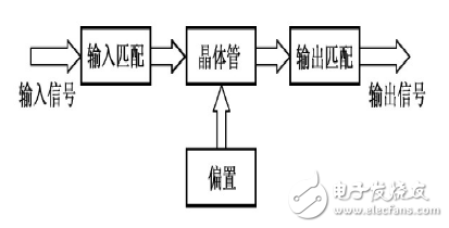
RF power amplifiers (RF PAs) play a crucial role in wireless communication systems, especially in transmitters. Before the signal is sent to the antenna, it must go through several stages of amplification. The RF signal generated by the modulating oscillator is typically weak, so it needs to be amplified through various stages—such as buffering, intermediate amplification, and finally, the power amplification stage. Only after gaining sufficient power can it be effectively radiated via the antenna. Therefore, an RF power amplifier is essential for achieving high output power.
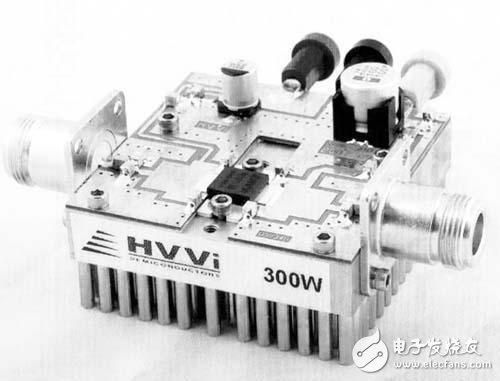
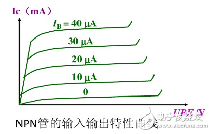
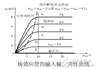
Today, power amplification is often achieved using integrated power amplifier chips, but the fundamental components are still triodes and field-effect transistors (FETs). These devices form the core of most RF amplifiers. Their input-output characteristics are illustrated in the diagram below.
Unlike traditional Class A, B, or C RF power amplifiers, modern RF amplifiers don’t require high voltages. They also have a narrower bandwidth compared to low-frequency power amplifiers. In particular, D-type FET amplifiers operate in a switching mode, which significantly reduces drain power dissipation. While these transistors spend only a short time in the linear region during switching, their high operating frequency and fast transition times result in much higher efficiency—often exceeding 90%.
D-type FET amplifiers usually consist of two or more pairs of transistors, divided into two groups to handle power amplification. The excitation voltage that drives the FETs into switching mode can be either a sine wave or a square wave. There are two main types of circuits: current-switching and voltage-switching. In high-frequency applications, the switching time becomes significant, so voltage-switching circuits are commonly used in medium-wave broadcast transmitters. These circuits come in two configurations: full bridge and half bridge.
The full-bridge power amplifier is widely used in modern medium-wave transmitters. It uses four FETs connected in a bridge configuration, operating in D-mode switching. This setup is known as an H-type amplifier. The full-bridge circuit consists of two half-bridges, with outputs connected to opposite ends of the primary coil of a transformer. This design resembles a traditional push-pull configuration. Each RF power amplifier is powered independently, and the drive signals are also applied separately to each bridge. Half-bridge operation is often used in the pre-driver stage of RF power amplifiers.
Cable Barcode Scanner,Barcode Scanner Cable,Symbol Scanner Cable,Barcode Scanner Usb Cable
Guangzhou Winson Information Technology Co., Ltd. , https://www.barcodescanner-2d.com