Multi-function inverter electricity talk about rectifier circuit in power electronics technology
Power electronics technology is a technology that transforms and controls electrical energy developed in the second half of the 20th century. It has become an important professional foundation course in electrical engineering and its automation. In the face of the increase of university courses and the reduction of professional course teaching time, reforming teaching content, methods, means and experimental teaching conditions is of great significance for improving teaching quality and cultivating innovative talents.
Key words: power electronics technology; rectifier circuit; pulse arrangement; rectified output voltage
First, the application of power electronics technology
Power electronics technology is an emerging technology. It is composed of three disciplines: electrical engineering, electronics and control theory. It has become an indispensable part of the electrical automation profession with strong professional foundation and close connection with production. Professional basic course. This course reflects the control of weak electricity to strong electricity, and it is also very practical. Being able to connect theory with practice and occupy an important position in cultivating automation professionals. It includes the structure and classification of thyristors, thyristor overvoltage and overcurrent protection methods, controllable rectifier circuits, thyristor active inverter circuits, thyristor passive inverter circuits, PWM control technology, AC voltage regulation, DC chopping, and The working principle of the frequency conversion circuit.
In power electronics technology, the controllable rectifier circuit is a very important chapter. The rectifier circuit is a circuit that converts alternating current into direct current, and its application is very extensive. Various types of DC motors used in the industry are regulated by power electronic devices; rectified power electronics are also widely used in transportation vehicles such as electrified railways (electric locomotives, maglev trains, etc.), electric vehicles, airplanes, ships, and elevators; Various electronic devices, such as a DC power supply for a program-controlled switch in a communication device, a working power supply for a large-sized computer, and a power supply for a microcomputer, can be powered by a DC power source composed of a rectifier circuit, and it can be said that there is a power source in a place where there is a power source. Technical equipment.
Second, the rectifier circuit in the power electronics technology course
The rectifier circuit can be divided into three types: uncontrollable, semi-controlled and full-controlled. The main components of the thyristor semiconductor device are semi-controlled and fully controlled rectification circuits. According to the circuit connection, it can be divided into bridge and zero. Rectifier circuit; according to the number of AC input phases can be divided into single-phase, multi-phase (mainly three-phase) rectifier circuit.
According to the law of students' acceptance of knowledge, the knowledge points are fully, accurately and concisely expressed, and the principle knowledge is as simple, popular and intuitive as possible. The author has conducted research and research in teaching, according to three forms of rectifier circuits. The circuit characteristics, load form, the main parameter calculation and main features are respectively made into a single-phase rectifier circuit induction table (see Table 1) and a three-phase rectifier circuit induction table (see Table 2).
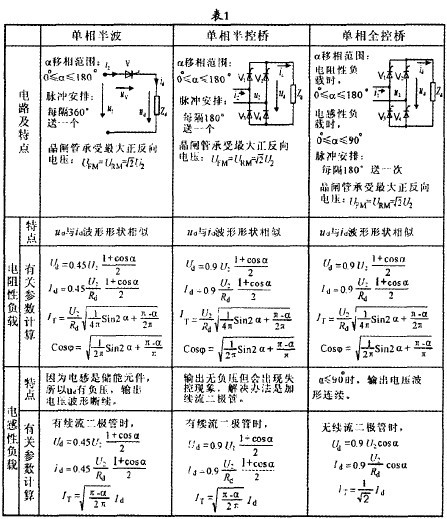
In the table, α - rectifier circuit control angle, UFM, UKM - thyristor with maximum forward and reverse voltage, U2 - transformer pay-side voltage rms, U4 - output voltage average, I4 - output current averaging, IT - Thyristor current efficiency value, Cos θ - circuit output power factor.
Third, the summary of the rectifier circuit in power electronics technology
Through the induction table, students can master the following aspects of the rectifier circuit through comparative learning methods:
(1) Arrangement requirements for various circuits for pulses
This is the most important point, because whether a rectifier circuit works properly, it is especially important that the pulse arrangement is correct. For a single-phase circuit, the cycle is 360°. If the circuit is half-wave, it consists of one thyristor, and one pulse is sent every 360°. If the circuit is a half-controlled bridge, it consists of two thyristors and two diodes, separated by 180°. (360°÷2=180°) sends a pulse; when the circuit is a full control bridge, it consists of four thyristors, which work in two groups. Like the half-controlled bridge, it sends a pulse every 180° (note here once) It means that the two thyristors are pulsed at the same time); for the three-phase rectifier circuit, the number of power supply phases is three times that of the single phase, so the pulse is arranged 1/3 times of the single phase, for example, the three-phase half-wave is 120° apart. (360°÷3=120) sends a pulse; the three-phase full control bridge is composed of 6 thyristors, which are turned on in turn. It is necessary to ensure that the two thyristors are turned on at the same time, so the interval is 60° (360°÷6=60). °) A pulse is sent to both thyristors.
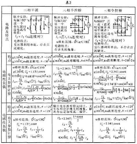
In the table, α—rectifier circuit control angle, UFM, UKM—transistor withstands the maximum forward and reverse voltage, U2—the effective value of the transformer's edge voltage, I2—the effective value of the transformer's side current, Ud—the average output voltage Value, Id - the average value of the output current. IT - the effective value of the transistor current, θ - the conduction angle of the transistor.
(2) Calculation of the average value of the output voltage of the rectifier circuit
The output voltage of the rectifier circuit refers to the average voltage of the circuit output. This parameter reflects the output of the circuit. Usually we choose the rectifier circuit, so it is a very important parameter. To allow students to remember the calculation formula of the output rectified voltage, it can be found from the table that for a single-phase rectification circuit, whether it is a resistive load or an inductive load, the output voltage can be expressed as Ud=AU2(1+Cosα)/2 Where A is the coefficient, if it is a single-phase half-wave, A=0.45, if it is a single-phase bridge, A=0.9 (twice the half-wave), only the single-phase full-control bridge inductive load is a special case, its output voltage It is Ud=0.9u2Cosα. Similarly, for the three-phase rectifier circuit, when the Ud waveform is continuous (Ud waveform continuous means that there is a rectified voltage output in one cycle, Ud=0 does not appear), the output voltage Ud=AU2Cosα. A is the coefficient. When the circuit is half-wave, A=1.17. When the circuit is a full-control bridge, A=2.34 (twice the half-wave), only the three-phase half-control bridge is a special case, and its output voltage is Ud. = 2.34U2(1+Cosα)/2.
(III) Calculation of the average value of the output current of the rectifier circuit
Whether single-phase or three-phase, whether it is a resistive load or an inductive load, the rectifier circuit output current is
Id=Ud/Rd (Rd is the resistance value in the load).
(4) Calculation of the maximum forward and reverse voltage of the thyristor
This parameter is an important parameter for selecting a thyristor. It can be seen from the table that for a single-phase rectification circuit, the maximum voltage of the thyristor is the peak value of the power supply phase voltage, that is, U2U2, and for the three-phase circuit, the maximum voltage of the thyristor is the peak value of the power supply line voltage. √6U2: (Because it is three-phase, the line voltage is different from the phase voltage by √3 times).
(5) Whether the output voltage Ud waveform is continuous or not
It can be seen from Table 1 that for the single-phase rectification circuit, when the control angle of the thyristor is α>0°, the waveform of ud is discontinuous, and only the single-phase full-control bridge inductive load, when α>90°, the waveform of ud is discontinuous. . As can also be seen from Table 2, for a three-phase rectifier circuit, the three-phase half-wave circuit is α = 30°. As the boundary point of the output voltage waveform continuous or not; and the three-phase bridge rectifier circuit (including the half-control bridge and the full-control bridge) is α=60° as the boundary point of the continuous or non-output voltage waveform.
From the table, we can also find out the calculation rules of other parameters. Because of the limited space, we will not list them here.
Fourth, the conclusion
Through the induction table of this single-phase and three-phase rectifier circuit, students can quickly grasp the structure, circuit characteristics and relevant calculation formulas of various rectifier circuits, so as to better grasp the basic theoretical knowledge of power electronics technology. Provided very helpful.
references:
[1] Zhao Dianjia. SCR circuit [M]. Beijing: Metallurgical Industry Press. 1980.
[2] Wang Zhaoan. Power Electronics Technology (4th Edition) [M]. Beijing: Mechanical Industry Press. 2006.
[3] Liu Yuxi. Power electronics technology and applications [M]. Xi'an: Xi'an University of Electronic Science and Technology Press, 2006.
[4] Jin Haiming. Power Electronics Technology [M]. Beijing: Beijing University of Posts and Telecommunications Press, 2006.
Silicone Rubber OH Line Cover,Silicone Rubber ,Liquid Silicone ,Silicone Sheets
Cable Sleeve Co., Ltd. , http://www.nbshrinktubing.com