Abstract: Use PC / 104 module 486DX and EMM-8M-XT to realize multi-serial communication. After expansion, 10 serial ports can carry out full-duplex communication at the same time. Combined with engineering examples, the system structure, software and hardware design methods and typical applications of multi-serial communication on DOS platform are given.
The revised draft was received on December 31, 2004.
Introduction Serial communication has many advantages, such as easy to use, reliable transmission, and a small number of signal lines.
Based on the embedded system of PC / 104 module, serial communication is one of the commonly used communication methods. Through the serial data port, PC / 104 and PC and PC / 104 module communication can be achieved. UAV flight control system is a typical multi-peripheral platform, so the problem of multi-serial port data communication must be solved in engineering design to complete data collection or signal transmission. In other engineering applications, it is especially important to study multi-serial data communication. Using PC / 104 modules to expand more than 8 serial ports in an embedded system and simultaneously carrying out duplex data communication is the focus of this article.
System structure and hardware design With the advancement of technology, the embedded module of PC / 104 structure can be expanded by a simple method of building blocks according to actual requirements. Its rich functional modules bring many conveniences for designers. In UAV flight control systems, some sensors, measurement and control terminals, and mission equipment usually use serial data interfaces. This article will combine a certain type of UAV flight control system development platform, introduce the application of 486DX and EMM-8M-XT embedded modules to achieve multi-serial data communication expansion design methods and engineering applications.
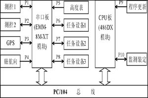
The structure of a certain UAV flight control system is shown in Figure 1. In actual use, the CPU board and the serial port board are connected through the PC104 bus stack, and other functional modules such as AD / DA, DIO, etc. are also expanded according to the needs of use. This article only introduces the modules related to the serial port. The system CPU board comes with two serial ports (P9 ~ P10), and the extended serial board provides 8 serial ports (P1 ~ P8) to complete different data communication functions. The specific functions and communication modes of each port are shown in Table 1.
Table 1 Serial port working mode and function Serial port number working mode function
P1, P2
RS422
For data communication with measurement and control equipment
P3
RS422
Receive GPS information and send initial information
P4
RS485
Collect heading angle data
P5
RS485
Collect altitude and airspeed data
P6 ~ P8
RS422
Data communication with 3 mission equipment
P9
RS232
CPU board electronic disk program update
P10
RS232
Flight control system monitoring, route setting Figure 1 System block diagram
486DX module 486DX is a highly integrated PC / 104 CPU module with self-stack structure and compatible with IBM-PC / AT. Using the enhanced 80486 embedded central processor INTEL DX4 as the core component, the operating frequency of 33 ~ 133MHz, 4 ~ 16M bytes of on-board DRAM.
The 486DX module contains a PC / AT compatible DMA controller, 8259 type interrupt controller and timer on the board, with extended industry standard ROM-BIOS and keyboard speaker interface. The external interface of the board includes a PC / AT compatible standard bidirectional parallel port, two 16550 compatible RS232 serial communication interfaces, an external backup battery to support real-time clock, application of EEPROM to store BIOS parameter settings, eliminating most of the hardware Configure jumpers. The power consumption of this board is extremely low, the typical value is 2.8W, the external power requirement is + 5V, and it can work in a wide temperature range.
The system designed in this paper mainly uses the two serial ports of the module. Port 1 (P9) is used to realize online rewriting of the user program on the electronic disk of the module. Port 2 (P10) is mainly used for real-time monitoring of flight control system parameters and route Pretend. Considering that there are many serial devices in the actually designed system, it is necessary to expand the serial port module to realize multi-serial communication. Here selects the EMM-8M-XT serial communication module of DIAMOND company to realize.
EMM-8M-XT module expansion design The EMM-8M-XT serial communication module integrates two high-performance 16C554 control chips (equivalent to eight 16C550) on the board, which can achieve a higher communication rate without taking up too much The main characteristics of the CPU resources and modules are as follows:
· Each channel has independent 16-byte receive buffer and 16-byte transmit buffer;
· Each serial port can set the working mode through hardware jumper (RS232 \ RS422 \ RS485 optional);
· The standard configuration baud rate can reach 115.200Kbps (460.8Kbps optional);
· 16 different I / O address items;
10 optional interrupt levels;
· The base address and interrupt selection of 8 serial ports are selected from the EEPROM at power-on, and can be configured by software after power-on;
In the EMM-8M-XT module, J3 and J4 are the serial ports of the module. In addition to including eight configurable full-signal serial ports, it also includes 8 discrete DIOs. In this example, no DIO is used. There are 5 groups of jumpers in the module including J5 ~ J9. By setting these jumpers correctly, you can determine the serial port working mode, base address and interrupt number. It should be noted here that since the serial port module is externally expanded, its address cannot conflict with the serial port address of the CPU module, so the jumper of J9 is set to B (in), C (in), and the base address of the serial board is 240H. The interrupt numbers used are 3 and 11. Among them, P1 ~ P4 share No. 11 interrupt, and P5 ~ P8 share No. 3 interrupt.

To use each serial port correctly, in addition to the correct hardware jumper settings, you must also set the software settings for the on-board EEPROM of the EMM-8M-XT module. The base address and interrupt number settings of each serial port are stored in the EEPROM. After power-on, the module will read these data, and the software setting of the interrupt number should be consistent with the hardware jumper settings.
It should be noted that once the serial port software is successfully set, this setting is the same as the hardware jumper setting effect, which is determined by the non-volatile nature of the EEPROM. Unless the rewriting operation is performed by software, the set parameters will be changed. In this example, the author has written a software setting application program with Borland C (for space limitation, this article is omitted). The software setting of the EEPROM for the EMM-8M-XT module can be performed on the PC / 104 development device, and after setting, Read and display to verify the correctness of the settings.
Software design The software is programmed in C language and works under DOS6.22 platform system. It has good readability and can be easily transplanted to other platforms. There are many modules in the serial communication program. Here is a brief introduction to the code of the serial service program of the EMM-8M-XT module as an example. The programming method of the 486DX module is similar. See Figure 2 for the basic flow of the software.
Figure 2 Basic process of serial port software
Server_COM_Int (CCOM * pCOM) serial port service program:
void Server_COM_Int (CCOM * pCOM) // Serial port service program
{
int nDataInBuf; // If there is an interrupt waiting for response while (! ((pCOM-> byteIIR = (0x0F & inportb (pCOM-> Base + COM_IIR)))
& COM_NO_INT_PENDING)) {
switch (pCOM-> byteIIR) {
case COM_INT_FROM_RDR: // Data is ready case COM_INT_FROM_RTO: // Receive timeout while (inportb (pCOM-> Base + COM_LSR) & COM_STATUS_DR) {// There is data in FIFO pCOM-> pRBuffer [pCOM-> pRBEndOff ++]
= inportb (pCOM-> Base + COM_RB); // Data enters ring buffer if (pCOM-> pRBEndOff == pCOM-> nRBSize)
pCOM-> pRBEndOff = 0; // adjust the ring buffer pointer}
pCOM-> bCOM_Data_OK = TRUE; // The serial receipt is completed break;
case COM_INT_FROM_TRE: // Send data ready nDataInBuf = pCOM-> pTBEndOff-pCOM-> pTBHeadOff; // Calculate the number of characters in the buffer if (nDataInBuf == 0) // If the number of characters is zero, prohibit "send empty" interrupt outb (pCOM-> Base + COM_IER,
inportb (pCOM-> Base + COM_IER) & (~ COM_INT_THRE));
else {
outportb (pCOM-> Base + COM_MCR, // Transmit enable, Bit1 is set to 1 (pull RTS low)
(inportb (pCOM-> Base + COM_MCR) | COM_MCR_RTS) & (~ COM_MCR_DTR));
if (nDataInBuf <0) nDataInBuf + = pCOM-> nTBSize; // Calculate the number of buffer characters if (nDataInBuf> COM_MAX_FIFO_DEP)
nDataInBuf = COM_MAX_FIFO_DEP;
while (nDataInBuf> 0) {
outportb (pCOM-> Base + COM_THB,
pCOM-> pTBuffer [pCOM-> pTBHeadOff ++]);
if (pCOM-> pTBHeadOff == pCOM-> nTBSize) pCOM-> pTBHeadOff = 0;
nDataInBuf--;
}
}
outportb (pCOM-> Base + COM_MCR, // Send prohibition, receive enable (inportb (pCOM-> Base + COM_MCR) & (~ COM_MCR_RTS)) | COM_MCR_DTR);
break;
}
}
}
Application situation In the application process, first use the self-editing software to test each module. Taking EMM-8M-XT as an example, the test process is divided into three steps: single serial port work → 4 serial ports work at the same time → 8 serial ports work at the same time. When testing 8 serial ports working at the same time, the serial port works in RS232 working mode. Connect the serial port module directly to 4 industrial control computers with a total of 8 serial ports. The send and receive counts displayed by the serial port modules are equal, indicating normal operation. At the same time, the serial port converter is connected to the industrial control computer, and the working modes of RS422 and RS485 are also tested. The results obtained are similar to RS232.
On the basis of successful debugging of a single module, a system joint test was carried out. The detailed configuration of the system is shown in Figure 1. The method of simulating peripheral equipment by industrial control computer or PC is still used for communication test. The development device of the PC / 104 module is equipped with a display, and the working status of each serial port is displayed on the screen. This article tested the situation of 9 serial ports working at the same time. Because the serial port P9 is used for program update, the user program is written through this port. For real-time communication. If P9 is not used for this function, 10 serial ports can communicate at the same time. It has been found through experiments that multiple serial ports can continuously and stably perform data transmission for a long time, and each serial port can be set to work with different baud rates.
In addition to a large number of normal temperature tests, a temperature test was also performed on the entire system. The module works normally at a high temperature of + 85 ° C and a low temperature of -40 ° C.
Multiple tests have shown that the system has a wide operating temperature range, strong anti-interference ability, good real-time performance and high reliability, and is suitable for UAV flight control systems and other industrial control occasions.
Conclusion In this paper, the C / 104 module 486DX and EMM-8M-XT realize the multi-serial communication expansion design method, which has been successfully applied to the design and development of a certain UAV flight control system. In the follow-up development work, with slight changes, the design method will also be used to develop a flight control system simulation platform, replacing the traditional scheme of using a desktop PC for simulation, and supporting the flight control system for simulation tests.
This serial port expansion design method is easy to master, the constructed system works stably, and has strong advantages in power consumption, volume, and cost, providing an important reference for the engineering implementation of multi-serial communication.

Follow WeChat

Download Audiophile APP

Follow the audiophile class
related suggestion
'+ data.data.username +' '; dom + ='
Function: The Cob Work Light has 1-5 modes;
Feature: The COB Work Light usually higher power and super bright than LED Work Light;
Trait: The products are waterproof, shockproof;
Method of application: Simple on/off push button operation;
Range of application: The COB Work Light for emergency events, camping, outdoor activities and indoor;
Adervantages: Our products are saled with factory price, and the quality can guarantee, lastly we provide warranty for 1 year.
COB Work Light
Cob Work Light,Cob Led Work Light,Cob Led Flashlight,Cob Flashlight
Ningbo Henglang Import & Export Co.,Ltd , https://www.odistarflashlight.com