This article will introduce the main circuit and control circuit of the forward and reverse of the three-phase asynchronous motor, as well as the external wiring diagram and ladder diagram of the PLC control system.
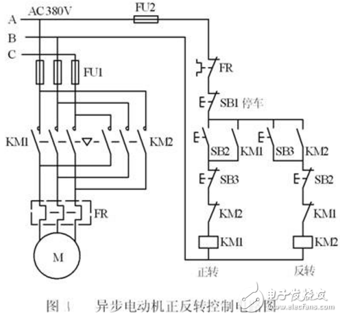
Figure 1 is the main circuit and relay control circuit diagram of the forward and reverse control of the three-phase asynchronous motor. Figures 2 and 3 are the external wiring diagram and ladder diagram of the same plc control system with functions, wherein KM1 and KM2 are control positive AC contactors that run and reverse run.
In the ladder diagram, two start-stop circuits are used to separately control the forward and reverse rotation of the motor. When the forward rotation start button SB2 is pressed, X0 is turned ON, its normally open contact is turned on, the coil of Y0 is "powered" and self-holding, the coil of KM1 is energized, and the motor starts to run forward. Pressing the stop button SB1, X2 turns ON, its normally closed contact is opened, the Y0 coil is "de-energized", and the motor stops running.
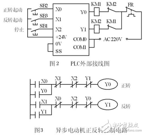
In the ladder diagram, the normally closed contacts of Y0 and Y1 are respectively connected in series with the coil of the other side, so that they are not turned ON at the same time, so the coils of KM1 and KM2 are not energized at the same time. This safety measure is called in the relay circuit. For "interlocking." In addition, for the convenience of operation and to ensure that Y0 and Y1 are not ON at the same time, "button interlock" is also set in the ladder diagram, that is, the normally closed contact of the start button X1 and the Y0 of the forward rotation are controlled. The coils are connected in series, and the normally closed contact of the forward rotation start button X0 is connected in series with the Y1 control inverted coil. Let Y0 be ON, the motor rotates forward. If you want to change the reverse rotation, you can press the reverse start button SB3 without pressing the stop button SB1. X1 turns ON, and its normally closed contact opens, making Y0 The coil is "de-energized", and the normally open contact of X1 is turned on, so that the coil of Y1 is "powered" and the motor changes from positive to negative.
The interlock and button interlock circuit in the ladder diagram can only ensure that the normally open contact core of the hardware relay corresponding to Y0 and Y1 in the output module will not be turned on at the same time. Due to the delay of the inductance during the switching process, there may be a phenomenon that the contactor has not been broken and the other has been closed, resulting in a short-circuit fault. This problem can be solved with the delay in forward and reverse switching, but this solution will increase the amount of programming work, and will not solve the power supply short circuit accident caused by the contactor contact failure.
If the main circuit current is too large or the quality of the contactor is not good, the main contact of a contactor is bonded by the arc welding caused by the power failure, and the main contact is still connected after the coil is de-energized. At this time, if the line diagram of the other contactor is energized, it will still cause a short-circuit of the three-phase power supply. In order to prevent this, a hardware interlock circuit consisting of auxiliary normally closed contacts of KM1 and KM2 should be set outside the PLC (see Figure 2). It is assumed that the main contact of KM1 is arc-welded, at which time it is combined with KM2. The auxiliary normally closed contact in series with the coil is in an open state, so the coil of the KM2 is unlikely to be energized.
The FR in Fig. 1 is a thermal relay for overload protection. When the asynchronous motor is seriously overloaded for a long time, after a certain delay, the normally closed contact of the thermal relay is opened, and the normally open contact is closed. The normally closed contact is connected in series with the coil of the contactor, and the contactor coil is de-energized when the motor is overloaded, and the motor stops running, thereby protecting.
Some thermal relays need to be manually reset. That is, after the thermal relay is activated, the reset button must be pressed to return its original position, that is, the common open contact is opened and the normally closed contact is closed. The normally closed contact of this thermal relay can be connected to the output loop of the PLC as in Figure 2, still in series with the coil of the contactor. This solution saves one input point of the PCL.
Some thermal relays have an automatic reset function, that is, the motor stops after the thermal relay is actuated, and the thermal relays of the thermal relays connected in series in the main circuit are cooled, and the contacts of the thermal relay are automatically restored to their original state. If the normally closed contact of the thermal breaker is still connected to the output circuit of the PLC, after the motor is stopped for a while, it will automatically re-operate due to the return of the contact of the thermal relay, which may cause equipment and personal accidents. Therefore, the normally closed contact of the thermal relay with automatic reset function cannot be connected to the output circuit of the PLC, and its contact must be connected to the input end of the PLC (can be connected to the normally open contact or normally closed contact), with ladder diagram To achieve overload protection of the motor. If an electronic motor overload protector is used instead of a thermal relay, attention should also be paid to its reset mode.
The Description of Wifi Rubber Antenna
Electrical Specifications
Frequency Range(MHz) 2300-2500
Gain(dBi) >5
V.S.W.R. <1.3
Polarization Vertical
Non-Circularity(dB) ±0.5
Impedance(Ω) 50
Lightning Protection Direct Ground
Maximum Input Power(W) 50
Mechanical Specifications
Connector Type SMA
Radiating Element Material Copper
Radome Material EVA
Radome Color Gray
Dimension (mm) 195Unbend) 173(Bend)
Wight(Kg) 0.09/12

Wifi Rubber Antenna Application Condition Indoor
Operating Temperature(℃) -40~+85
Reposition Temperature(℃) -55~+100
Connects internal WiFi to external WiFi Booster Antenna
Can be used with both indoor and outdoor antennas
Compatible with 802.11a, 802.11b, 802.11g, and 802.11n
DAS (Distributed Antenna Systems)
900MHz and Cellular applications
GSM/DCS/AWS/PCS/WCDMA/3G applications
IEEE 802.11b/g applications
Wifi Rubber Antenna,Indoor Wifi Rubber Antenna,Wifi Black Rubber Antenna,High Gain Wifi Rubber Antenna
Yetnorson Antenna Co., Ltd. , https://www.yetnorson.com