Spatial multiplexing multiple-input multiple-output (MIMO) transmitters and receivers are said to improve the performance of wireless communication systems more than their existing single-input single-output (SISO) counterparts. Next-generation wireless standards, such as 802.11n, will support data transmission rates of up to 600 Mbps and wireless LAN transmission rates in excess of 1 GHz.
However, the design of these systems must make a compromise between cost and power consumption, which has an important impact on battery-operated handheld devices. The challenge for design teams is to find the best balance between these design requirements for their specific applications.
The core of this technology is the concept of multipath, which is the reflection of radio frequency (RF) signals in a physical environment. Although multipath issues degrade the performance of existing 802.11 devices, spatial multiplexing orthogonal frequency division multiplexing (OFDM) MIMO—a key element in the 802.11n standard—uses these reflections to "tune" The transmitter minimizes errors and improves overall performance. But in these bandwidths, the scattering, diffraction and absorption of microwaves by objects located in the transmission path are an important consideration. When designing a MIMO system, it is necessary to describe these effects as accurately as possible in the form of a channel model.
There are three basic sources of channel models: software-based mathematical models, generally from the standards committee; hardware-based MIMO channel simulators, designed by themselves or provided by companies such as Azimuth; the best is the real MIMO system will run World environment. Verification of MIMO systems in the real world requires the ability to quickly build transmitter and receiver prototypes on MIMO-oriented FPGA hardware platforms, such as Lyrtech ’s VHS-ADC-V4 card.
MIMO performance advantages The advantage of spatial multiplexing MIMO technology is that it can increase the transmission speed through the number of antennas. The data rate of the existing SISO system is determined by the following formula:
R = Es * Bw
Where R is the data rate (bits / sec), Es is the spectral efficiency (bits / sec / Hz), and Bw is the communication bandwidth (Hz). For example, for the 802.11a standard, the peak data rate is determined by the following formula:
Bw = 20 MHz
Es = 2.7 bps / Hz
R = 54 Mbps
When using MIMO, an additional variable "Ns" needs to be introduced into the formula, which represents the number of independent data streams simultaneously transmitted through different spatial paths using the same bandwidth. Now the spectrum efficiency will be calculated according to the transmission / stream Ess, so the data rate of the MIMO system becomes:
R = Ess * Bw * Ns
We compare the previous 802.11a example with the results that can be obtained from the current 802.11n proposal, using a 20 MHz bandwidth and four antennas:
Bw = 20 MHz
Ess = 3.6 bps / Hz
Ns = 4
R = 288 Mbps
The use of MIMO technology has enabled the 802.11n standard of the project to achieve a 5.3 times increase in data rate.
MIMO system hardware complexity The performance improvement of the spatial multiplexing MIMO system is obtained at the cost of increasing the hardware complexity. A transmission / reception system using multiple antennas not only transmits data between corresponding antennas, but also transmits data between adjacent antennas. As you can see in Figure 1, the data is received in the form of "MIMO channel matrix".
In the process of decoupling the channel matrix in the spatial domain and recovering the transmitted data, linear geometric techniques such as singular value decomposition (SVD) or matrix inversion are required. The backward compatibility requirements for the 802.11g standard limit the number of antennas in the 802.11n standard to two or four, thereby limiting the size of the channel matrix to 2 x 2 or 4 x 4.
The development of a MIMO system prototype that implements the actual system data rate on hardware requires the use of an FPGA-based hardware platform. Xilinx® Virtex ™ -4 series FPGAs provide performance far superior to DSP processors for such applications by providing up to 512 hardware multipliers that can perform parallel operations. However, when designing such a prototype system, you will face two major challenges: the first challenge is to use hardware to design something as complex as SVD or matrix inversion, and the second challenge is to adjust the implementation to make it To achieve optimal performance.
Selecting a dedicated SVD or matrix inversion algorithm in the implementation of matrix operations on an FPGA will be a compromise between numerical stability and hardware efficiency. You need to develop an advanced MATLAB model to determine the most efficient algorithm for a particular application.
In the case of SVD, this may involve choosing between adaptive estimation techniques, vector rotation, or other simplified techniques that result from channel matrices that have characteristics such as symmetry.
Once the algorithm is finalized, you will need to adjust the hardware performance to match the overall system requirements. To maximize the performance of the MIMO system in hardware, it is required to use partial parallel multiplication in the key places in the design that will have the greatest impact on the overall performance. The given rotation algorithm shown in Figure 2 gives a good example of performance improvement through parallel multiplication.
By using the MATLAB algorithm as the golden source code for FPGA development and eliminating the need to rewrite to other languages ​​or design environments, the number of development and verification cycles is reduced. The given rotation is usually used to solve the symmetric eigenvalue problem, and is the key building block of QRD matrix inversion.
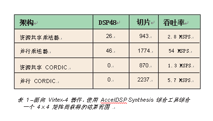
You can use a multiplier or CORDIC approximation to implement the algorithm. The design exploration capabilities of Xilinx's AccelDSP â„¢ Synthesis synthesis tool are used to improve performance by embedding parallelism into the architecture without rewriting code. As shown in Table 1, this method can achieve up to 10 times better performance than parallel CORDIC. Algorithms based on a given rotation have recently received more attention because they are themselves well suited for parallel implementation.
A FPGA-based FPGA design flow
The MathWorks' MATLAB provides a truly unique environment for the design and implementation of spatially multiplexed MIMO systems. The inherent language support for loops, complex numbers, vector and matrix operations, and mathematical functions provide an efficient modeling environment for the linear geometric algorithms required by MIMO.
Figure 3 demonstrates the advantages of the AccelDSP Synthesis synthesis tool,
This includes the flexibility of using floating-point MATLAB to define and implement custom architectures for spatially multiplexed MIMO systems on FPGAs.
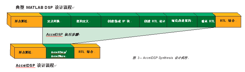
The automatic conversion function of floating point to fixed point can help solve complex quantization problems caused by the iterative nature of linear geometric functions such as SVD. Once you have determined an acceptable fixed-point model, you can quickly explore the trade-off between performance and hardware through algorithm synthesis, and quickly increase the number of dedicated hardware multipliers to improve performance and take full advantage of the flexibility of the Virtex-4 architecture.
The RTL generated from AccelDSP Synthesis is automatically verified against the golden-source MATLAB to confirm the bit-true functional correctness.
Conclusion By using MATLAB-based design flow in the development of channel matrix DSP hardware, the prototype design of the spatial multiplexing MIMO system for real-world verification is greatly simplified. By using the MATLAB algorithm as the golden source code for FPGA development and eliminating the need to rewrite to other languages ​​or design environments, the number of development and verification cycles is reduced. In addition, the advanced nature of MATLAB also enables the AccelDSP Synthesis synthesis tool to quickly explore hardware alternatives suitable for an algorithm, including the use of DSP blocks, RAM, and pipelines.
Both the AccelDSP Synthesis synthesis tool and the Lyrtech prototyping environment include an interface to the Xilinx System Generator for DSP design environment to provide an automated MATLAB to prototyping design flow.
However, the design of these systems must make a compromise between cost and power consumption, which has an important impact on battery-operated handheld devices. The challenge for design teams is to find the best balance between these design requirements for their specific applications.
The core of this technology is the concept of multipath, which is the reflection of radio frequency (RF) signals in a physical environment. Although multipath issues degrade the performance of existing 802.11 devices, spatial multiplexing orthogonal frequency division multiplexing (OFDM) MIMO—a key element in the 802.11n standard—uses these reflections to "tune" The transmitter minimizes errors and improves overall performance. But in these bandwidths, the scattering, diffraction and absorption of microwaves by objects located in the transmission path are an important consideration. When designing a MIMO system, it is necessary to describe these effects as accurately as possible in the form of a channel model.
There are three basic sources of channel models: software-based mathematical models, generally from the standards committee; hardware-based MIMO channel simulators, designed by themselves or provided by companies such as Azimuth; the best is the real MIMO system will run World environment. Verification of MIMO systems in the real world requires the ability to quickly build transmitter and receiver prototypes on MIMO-oriented FPGA hardware platforms, such as Lyrtech ’s VHS-ADC-V4 card.
MIMO performance advantages The advantage of spatial multiplexing MIMO technology is that it can increase the transmission speed through the number of antennas. The data rate of the existing SISO system is determined by the following formula:
R = Es * Bw
Where R is the data rate (bits / sec), Es is the spectral efficiency (bits / sec / Hz), and Bw is the communication bandwidth (Hz). For example, for the 802.11a standard, the peak data rate is determined by the following formula:
Bw = 20 MHz
Es = 2.7 bps / Hz
R = 54 Mbps
When using MIMO, an additional variable "Ns" needs to be introduced into the formula, which represents the number of independent data streams simultaneously transmitted through different spatial paths using the same bandwidth. Now the spectrum efficiency will be calculated according to the transmission / stream Ess, so the data rate of the MIMO system becomes:
R = Ess * Bw * Ns
We compare the previous 802.11a example with the results that can be obtained from the current 802.11n proposal, using a 20 MHz bandwidth and four antennas:
Bw = 20 MHz
Ess = 3.6 bps / Hz
Ns = 4
R = 288 Mbps
The use of MIMO technology has enabled the 802.11n standard of the project to achieve a 5.3 times increase in data rate.
MIMO system hardware complexity The performance improvement of the spatial multiplexing MIMO system is obtained at the cost of increasing the hardware complexity. A transmission / reception system using multiple antennas not only transmits data between corresponding antennas, but also transmits data between adjacent antennas. As you can see in Figure 1, the data is received in the form of "MIMO channel matrix".
In the process of decoupling the channel matrix in the spatial domain and recovering the transmitted data, linear geometric techniques such as singular value decomposition (SVD) or matrix inversion are required. The backward compatibility requirements for the 802.11g standard limit the number of antennas in the 802.11n standard to two or four, thereby limiting the size of the channel matrix to 2 x 2 or 4 x 4.
The development of a MIMO system prototype that implements the actual system data rate on hardware requires the use of an FPGA-based hardware platform. Xilinx® Virtex ™ -4 series FPGAs provide performance far superior to DSP processors for such applications by providing up to 512 hardware multipliers that can perform parallel operations. However, when designing such a prototype system, you will face two major challenges: the first challenge is to use hardware to design something as complex as SVD or matrix inversion, and the second challenge is to adjust the implementation to make it To achieve optimal performance.
Selecting a dedicated SVD or matrix inversion algorithm in the implementation of matrix operations on an FPGA will be a compromise between numerical stability and hardware efficiency. You need to develop an advanced MATLAB model to determine the most efficient algorithm for a particular application.
In the case of SVD, this may involve choosing between adaptive estimation techniques, vector rotation, or other simplified techniques that result from channel matrices that have characteristics such as symmetry.
Once the algorithm is finalized, you will need to adjust the hardware performance to match the overall system requirements. To maximize the performance of the MIMO system in hardware, it is required to use partial parallel multiplication in the key places in the design that will have the greatest impact on the overall performance. The given rotation algorithm shown in Figure 2 gives a good example of performance improvement through parallel multiplication.
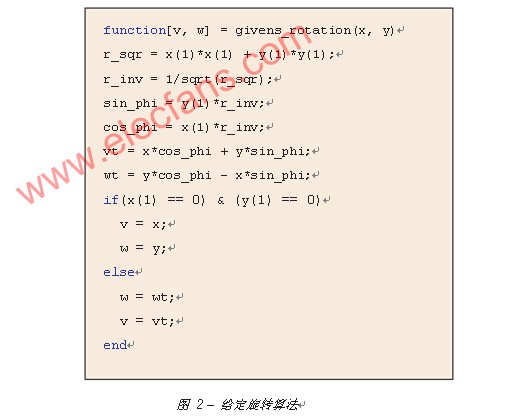
By using the MATLAB algorithm as the golden source code for FPGA development and eliminating the need to rewrite to other languages ​​or design environments, the number of development and verification cycles is reduced. The given rotation is usually used to solve the symmetric eigenvalue problem, and is the key building block of QRD matrix inversion.
You can use a multiplier or CORDIC approximation to implement the algorithm. The design exploration capabilities of Xilinx's AccelDSP â„¢ Synthesis synthesis tool are used to improve performance by embedding parallelism into the architecture without rewriting code. As shown in Table 1, this method can achieve up to 10 times better performance than parallel CORDIC. Algorithms based on a given rotation have recently received more attention because they are themselves well suited for parallel implementation.
A FPGA-based FPGA design flow
The MathWorks' MATLAB provides a truly unique environment for the design and implementation of spatially multiplexed MIMO systems. The inherent language support for loops, complex numbers, vector and matrix operations, and mathematical functions provide an efficient modeling environment for the linear geometric algorithms required by MIMO.
Figure 3 demonstrates the advantages of the AccelDSP Synthesis synthesis tool,
This includes the flexibility of using floating-point MATLAB to define and implement custom architectures for spatially multiplexed MIMO systems on FPGAs.
The automatic conversion function of floating point to fixed point can help solve complex quantization problems caused by the iterative nature of linear geometric functions such as SVD. Once you have determined an acceptable fixed-point model, you can quickly explore the trade-off between performance and hardware through algorithm synthesis, and quickly increase the number of dedicated hardware multipliers to improve performance and take full advantage of the flexibility of the Virtex-4 architecture.
The RTL generated from AccelDSP Synthesis is automatically verified against the golden-source MATLAB to confirm the bit-true functional correctness.
Conclusion By using MATLAB-based design flow in the development of channel matrix DSP hardware, the prototype design of the spatial multiplexing MIMO system for real-world verification is greatly simplified. By using the MATLAB algorithm as the golden source code for FPGA development and eliminating the need to rewrite to other languages ​​or design environments, the number of development and verification cycles is reduced. In addition, the advanced nature of MATLAB also enables the AccelDSP Synthesis synthesis tool to quickly explore hardware alternatives suitable for an algorithm, including the use of DSP blocks, RAM, and pipelines.
Both the AccelDSP Synthesis synthesis tool and the Lyrtech prototyping environment include an interface to the Xilinx System Generator for DSP design environment to provide an automated MATLAB to prototyping design flow.
ST Model Outdoor String Light set is waterproof and durable. Can be used in any season and many applications such as wedding, party, garden etc. We have different wire model and Replacement Bulb type to choose.
Decorative string lights are not just for holidays anymore . Instantly transform indoor and outdoor spaces with a wide selection of covers and finishes that match current trends and personal tastes and expressions.
Celebrate any season ,event or inspired whim with a charming new set of outdoor string lights!
String Light For Garden,Led T40 Bulb String Light,Vintage Light String,Led Light String
DONGGUAN JIANXING LIGHTING ELECTRIC APPLIANCES CO., LTD , https://www.rslightstring.com