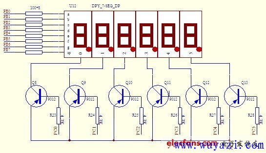
Dynamic Scan Display: The diagram below illustrates the dynamic scanning circuit for six common anode LEDs. In this setup, port B of the 8155 chip is connected to the dp (decimal point), g, f, e, d, c, b, and a segments of all the LEDs. Meanwhile, each LED's control terminal G—represented as 0, 1, 2, 3, 4, and 5 inside the digital display shown in the figure—is linked to the C port of the 8155. This configuration makes port B the "segment" port and port C the "digit" port. As a result, the CPU can control which LED lights up by sending signals through the C port. This method allows for efficient use of microcontroller resources when displaying multiple digits on a single LED display.
This technique is widely used in seven-segment displays where only one digit is illuminated at a time, creating the illusion of a full display due to the persistence of vision. It reduces power consumption and simplifies the wiring, making it ideal for applications such as digital clocks, calculators, and other electronic devices that require numeric output. Understanding how the 8155 chip manages these connections is essential for anyone working with embedded systems or digital electronics.
Solar Mounting System,Solar Water Panel Stand,solar panel metal ground mount,ground mounted solar
Hebei Jinbiao Construction Materials Tech Corp., Ltd. , https://www.pvcarportsystem.com