0 Preface
Compared with traditional incandescent lamps and fluorescent lamps, LEDs are environmentally friendly, energy-saving, long-lived, and shock-resistant. Therefore, in the context of global energy shortages, LEDs have become a research hotspot in the lighting industry. Since the quality of the LED driving power supply directly affects the reliability of the LED lighting product, and the LED driving power supply is currently the highest failure rate in the entire LED lighting system, with the continuous expansion of the LED application field, the development is safe, reliable, and efficient. The small size and long life of the LED drive power supply has become an inevitable trend.
1 LED drive circuit
The light intensity of an LED is proportional to the magnitude of its forward current. A small voltage change across the LED causes a large change in the current flowing through the LED, causing a significant change in light intensity. Therefore, constant current control is usually used for LEDs to keep the luminous intensity constant.
1. 1 LED constant current drive circuit topology
For LED circuits of different power levels, different drive circuit topologies should be chosen to achieve a balance between performance and cost.
1. 1. 1 Low-power LED lighting systems generally do not require power factor correction, so simple topologies such as Primary Side Regulation (PSR) or Buck topology can be used. PSR technology minimizes the cost of LED drivers. As shown in Figure 1, the circuit only needs to collect the current information of the primary of the transformer to accurately control the LED current at the secondary side, which not only eliminates the output current detection loss, but also eliminates all secondary feedback circuits, reducing cost and improving efficiency. .

Figure 1 Flyback converter with PSR control technology
1. 1. 2 For medium-power LED lighting applications, power factor correction is generally required. Therefore, single-stage PFC or flyback converter using Quasi-Resonance (QR) technology is generally used. The single-stage LED driver circuit has the advantages of simple structure, few components, and low cost, but the output ripple is large, which has advantages in the application of medium power LED lighting systems with low performance requirements. The basic principle of the quasi-resonant technology is to use the capacitance between the two ends of the MOSFET (parasitic capacitance or external capacitor) and the primary side leakage inductance of the transformer to drive the load, and control the near zero voltage of the switching tube by detecting the valley voltage at both ends of the switching device in real time. This reduces the switching losses of the MOSFET, improves the efficiency of the converter, and reduces EMI noise, as shown in Figure 2.

Figure 2: Flyback transformation using QR technique
1. 1. 3 High-power LED lighting systems typically use a two-stage PFC or LLC topology. The two-stage PFC has better performance due to the separate primary PFC, but the cost is higher. The LED drive circuit (shown in Figure 3) with LLC resonant conversion has many advantages, such as high switching frequency and switching loss. Small, allowable input voltage range, high efficiency, light weight, small size, low EMI noise, low switching stress, etc.
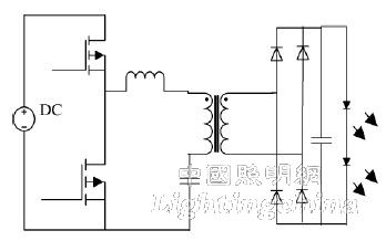
Figure 3 LED drive circuit based on LLC converter
1. 2 de-electrolytic capacitor LED drive circuit solution
LED lighting is mostly powered by utility power, but LEDs require DC drive, so a rectifier module is required in the circuit. Usually, in order to obtain the specified PF value, it is also necessary to add a PFC circuit. Because the input power is pulsating and the output power is constant, a large capacitance electrolytic capacitor must be used to balance the instantaneous power difference across the input and output. The presence of an electrolytic capacitor reduces the life of the LED drive circuit. If the electrolytic capacitor is simply removed, the output current will be greatly pulsated, and the PF of the circuit will be lower. If the electromagnetic energy storage is used instead of the capacitor, the circuit will be bulky. Therefore, research on other de-electrolytic capacitor LED drivers. The circuit scheme is necessary.
1. 2. 1 Based on the small ripple current can be used to drive the LED considerations, the LC filter circuit is added on the output side while the electrolytic capacitor is removed, and the 3rd and 5th harmonic currents are injected into the input current to make the power The factor meets the requirements and reduces the peak-to-average ratio of the LED current. However, this method will cause LED flashing because the output current contains twice the AC current of the grid frequency. Working under the flashing light source for a long time will increase the burden on the eyes and even cause eye damage.
1. 2. 2 Another scheme is shown in Figure 4. The design of the circuit is to control the current flowing through the bidirectional Buck-Boost auxiliary loop to equal the AC component of the grid frequency twice that of the grid, thereby indirectly controlling the flow. The current through the LED remains constant to avoid LED flashing. However, this solution is less efficient due to the need to add multiple additional devices.

Figure 4: Electroless capacitor LED driver circuit using auxiliary circuit
1. 2. 3 In the literature, the sinusoidal current or square wave current with a ratio of peak to average is less than 1.4 to drive the LED, and the reference signal is generated by the sinusoidal current generating circuit or the square wave current generating circuit to obtain the required current. The signal is used to drive the LED directly, and the input side can achieve a high power factor, but the control method is complicated.
The LED drive scheme of electroless capacitors still has many shortcomings, such as complicated system control, high power factor, slow system startup, and sensitivity to lightning strikes. Currently, it is only used in small and medium power LED lighting systems. Further research is needed for its wider application.