At present, personal computers (PCs) have been widely used, and the USB interface has become one of the standard peripheral interfaces on PCs. On the other hand, portable devices such as mobile phones, digital cameras, and MP3 players using lithium-ion batteries have appeared in large numbers.
However, how to use the ubiquitous computer USB interface to charge the lithium-ion battery used in these devices is a hot spot in the current USB interface application. In view of this, this paper proposes three options for the design of lithium-ion battery charging circuit based on USB interface. We can choose different solutions according to the actual situation such as use and cost to meet different requirements.
1 Lithium-ion battery and USB interface overview
Lithium-ion (Li-ion) battery, referred to as lithium battery "http://bbs.dianyuan.com/tech/battery", is a new type of battery that has been widely used in recent years. It has small size, light weight and large capacity. High energy density), low self-discharge rate and no memory effect, but it also has some fatal defects: the requirements for charging and discharging are more demanding, and can not be overcharged and over-discharged, otherwise it will easily cause irreversible damage. In extreme cases such as short circuit and overcharge, explosions may occur and cause danger.
Generally, the nominal voltage of a single lithium battery is 316~317V. When charging, it is generally required to use a voltage limiting current limiting method. First, constant current charging, that is, the current is constant, and the charging current is 0.2C at a low rate according to the national standard (arbitrary charging). System), the maximum does not exceed 1C; and the battery voltage gradually increases with the charging process, when the battery terminal voltage reaches the termination voltage 412 ± 0105V, the constant current charging should be changed to constant voltage and small current (about 011C) charging, this state is generally It is called trickle charge state. The charging current is gradually reduced according to the saturation degree of the cell as the charging process continues, and when it is reduced to 0101C, the charging is considered to be terminated.
The USB interface is an abbreviation of English UniversalSerialBus, and the Chinese meaning is "Universal Serial Bus". It is a new interface technology for PC applications. USB uses a 4-pin plug as a standard plug to connect to external devices. In this 4-pin plug, two pins are data communication lines, while the outer two pins provide power to external devices. According to the USB specification, each USB interface should be able to provide 500mA current output; the USB interface provided by the USB host or the hub with power supply, the minimum available voltage of the connected peripheral terminal is 4.5V, and the hub driven by the USB bus can provide The minimum should be 4.35V. It is worth noting that although the USB specification defines that the current limit provided must not exceed 015A, in practice the USB port output current often exceeds a few amps.
It can be seen from the above analysis that using the USB interface to charge the lithium battery, the current should be sufficient, the key is how to control the current. In addition, when using a USB interface with a minimum voltage of 4.35V to charge a typical lithium battery of 4.2V, there is only a small margin on the voltage, which makes the voltage drop of the charging circuit extremely important, which is a design difficulty.
2 PC-based USB interface charging circuit design
Option One
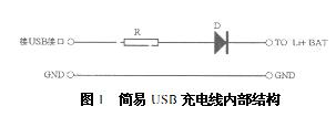
Figure 1 shows the internal circuitry of some "USB charging lines" on the market. The main principle is to use the resistor to limit the maximum current, and use the voltage drop of the diode (about 0.7V) to reduce the output voltage of the USB interface to about 4.2V and then charge the lithium battery. This circuit has the advantages of simplicity and low cost, but the disadvantages are also obvious: the charging current and the charging voltage vary depending on the USB interface and the state of the battery, and it is basically impossible to grasp. In many cases, the battery is likely to be unsatisfactory. (The charging voltage is less than 4.2V), and sometimes it may overcharge and damage the battery. This circuit is acceptable for some lithium batteries with perfect protection circuits inside, but it is dangerous for ordinary lithium batteries.
Option II
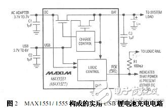
Figure 2 is a practical USB lithium battery charging circuit composed of MAX1551/1555. The MAX1551/1555 is a USB single-cell Li-Ion battery charger designed and manufactured by MAXIM. It is available in a 5-pin thin SOT23 package that allows USB input or wall AC adapter voltage input from 3.7V to 7V. The chip also has a temperature limiting circuit inside.
For this circuit, when connected to the USB port but without the DC power supply of the wall AC adapter, the charging current is set to 100 mA (maximum value). This allows charging from a powered or unpowered USB port without the need for port communication. When the DC power is turned on, the charging current is set to 280 mA (typical) and the input to the USB interface is automatically cut off. If there is no voltage input on both inputs, the circuit will automatically cut off. At this time, the reverse leakage current of the battery is less than 5uA, and no external diode is needed to prevent the battery from leaking and loss.
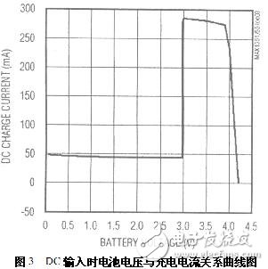
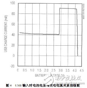
When the battery voltage is lower than 3V, the charging current is limited to 40mA pre-charging mode (thorch charging state), and the normal charging mode (100mA or 280mA) is entered only when the battery is charged above 3V. This mode protects the deeply discharged battery. Figures 3 and 4 show the relationship between the battery voltage and the charging current using the DC power box USB interface as input.
In addition, for the MAX1551 ", /POK" is used to indicate whether the input power is turned on (output low when the input voltage is 3.95V); and for the MAX1555 ", /CHG" is used to indicate the charge status (output when the charge current is greater than 50mA) Low level).
MOSO UFO High Bay LED Driver have the character of high power factor, high efficiency, high reliability and high-precision constant current. The UFO led driver owns a complete of function, various specifications can meet more different parameter of customers` requirement.


MOSO Intelligent innovator UFO shape led power has the led driver industry ' s unique derating over temperature protection circuit , which can make the light power supply not easy suddenly happen the phenomenon of over - temperature and shutdown even under the harsh working environment , so as to ensure continuous illumination.
The efficiency of the led driver supply is high and the power consumption is small. Accordingly, the heat in the lamp is small, then it reduce the temperature rise of the lamp. It is more advantage to delay the light decay of LED.
This Circular high-bay lighting drivers creatively integrated limited power, 0~10V/PWM dimming, dali control is optional.
Dali Industrial Light LED Driver complied with CCC/CE/ENEC/UL/SAA/CB safety regulations. Surge immunity is DM-4KV,CM-6KV.
High Bay LED Driver,Waterproof High Bay LED Driver,Modern High Bay LED Driver,UFO High Bay LED Driver
Moso Electronics , https://www.mosoleddriver.com