Specializing in the production of LED chip LED LED lamp beads
Circuit Operation Principle The disinfectant generator circuit is mainly composed of a power conversion circuit, an indicator control circuit, an electrode driving circuit and a timer circuit, as shown in Figure 9-93.
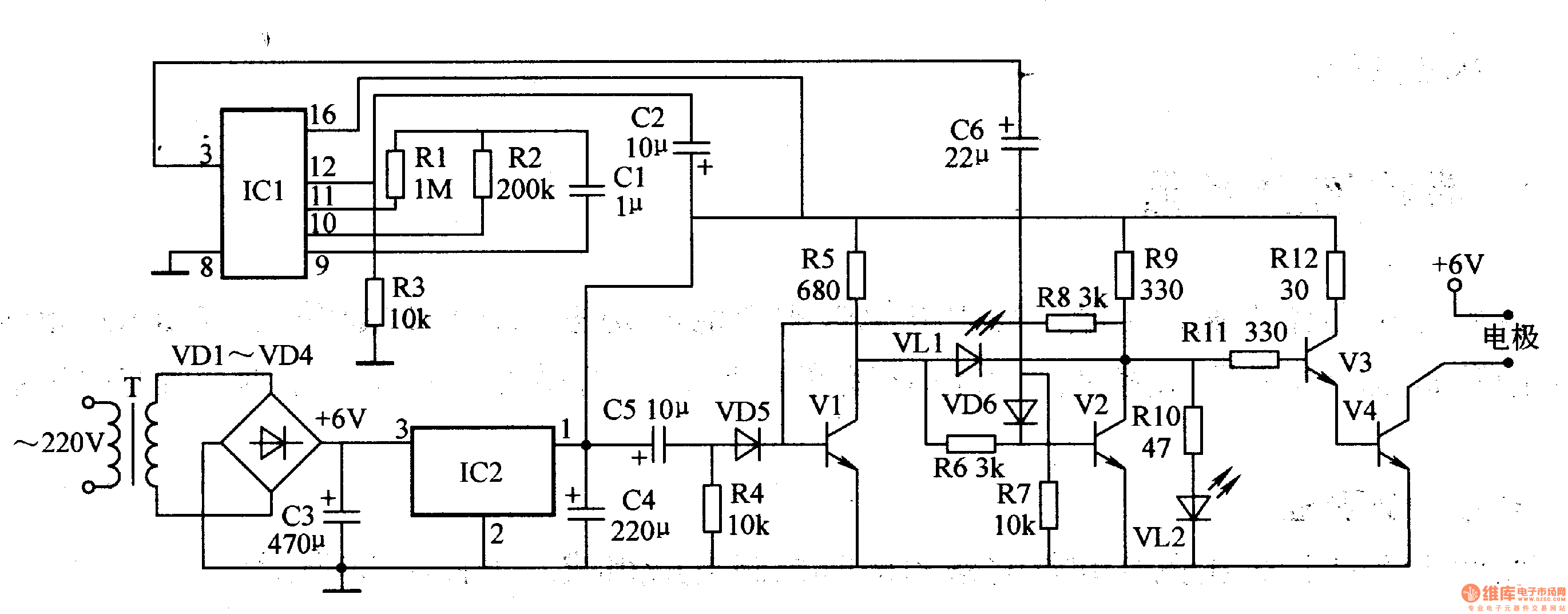
The power conversion circuit is composed of a power transformer T, a rectifier diode VDl-VD4, a filter capacitor C3 and a 5V three-terminal integrated voltage regulator IC2.
The indicator control circuit is composed of transistors V1, V2, LEDs VLl, VL2 and related peripheral components. Its application, Vl, V2 constitute an RS flip-flop, capacitor C5, resistor R4 and diode VD5 constitute the trigger circuit of the Vl input terminal, C5, R4 determine the width of the trigger pulse. C6, R7 and VD6 form the trigger circuit of the V2 input.
The electrode driving circuit is composed of transistors V3 and V4, resistors R11 and R12, and electrodes.
The timer circuit is composed of a counter integrated circuit ICl, a resistor Rl-R3, a capacitor Cl, a C2, etc., wherein RI and Cl are timing elements of ICl, and R3 phase C2 constitutes a reset circuit.
Install 500m1 brine in the cup of the disinfectant generator (enlarge a spoonful of salt), then turn on the power, AC 220V voltage through T step-down, VDl-VD4 bridge rectification and C3 filter, generate +6V voltage This voltage is directly supplied to the electrode and its driving circuit; the other circuit is regulated to +5V by IC2, and then supplied to the timing circuit, the indicator control circuit and the electrode driving circuit respectively. The transistor V1 is turned on under the trigger of C5, R4, and VD5, so that V2 is turned off, V3 and V4 are turned on, the electrode is energized, and the brine is electrolyzed. At this time, the green light emitting diode VL2 emits light, indicating the start of the work.
After the timer circuit is reset, counting starts from zero, and pin 3 (output terminal) of lC1 is low. When the timer works to about 60 minutes (the division depends on the values ​​of Rl and Cl), the 3 pin of IC1 goes high, and V2 is triggered by C6, R7 and VD6, and V2 is turned on, and its collector is powered by high voltage. The level is changed to a low level, and Vl, V3, and V4 are all turned off, and the electrodes are stopped. At this time, the green LED VL2 is turned off, and the red LED VLl is illuminated, indicating that the disinfectant has been made.
Component selection
Rl-Rll selects 1/8W metal film resistor or carbon film resistor for use; Rl2 selects 1/2W metal film resistor or carbon film resistor for use.
Cl uses button electrolytic capacitors or poly capacitors; C2-C6 selects aluminum electrolytic capacitors with a withstand voltage of lOV.
VDl-VD4 selects 1N4007 type silicon rectifier diode for use; VD5 and VD6 select 1N4148 type switching diode for use.
VLl and VL2 select φ3mm high-brightness light-emitting diodes, VLl selects red, VL2 selects green.
V1-V3 selects S9013 type low power NPN transistor for use; V4 selects BU406, BUTllA type and other high power transistors.
ICl selects CD4046 type integrated circuit for use; IC2 selects 5V low-dropout three-terminal integrated voltage regulator of MC78L05CP and other models.
T selects 5-8W, 6V small transformer.
Both electrode sheets are made of corrosion-resistant alloy material, and the shape should be suitable for fixing, installation and wiring. Usually, it can adopt "L" shape. The surface of the electrode sheet should be smooth and smooth without burrs, cracks, missing edges and other mechanical damage. The two electrode sheets should be installed in parallel and kept parallel to the bottom surface of the cup. The electrode sheet and the cup should be bonded with epoxy resin, which must be firmly bonded and prevent water leakage. A soldering piece is fixed on the electrode sheet by screws, and then the two soldering pieces are respectively connected with the +6V voltage terminal and the V4 collector electrode by wires.
ANC Headphones,ANC In Headphones,Best Anc Headphones,Gaming Noise Cancelling Headphones
TOPWAY EM ENTERPRISE LIMITED , https://www.topwayemltd.com