An amplifying circuit that has an output signal at the output with an input signal at the input. If there is no external input signal at the input end, the output terminal still has a certain frequency and amplitude signal output. This phenomenon is called self-oscillation of the amplifying circuit. The oscillating circuit is a circuit that generates a sine wave output voltage by self-oscillation of the circuit without an external input signal. It is widely used in remote control, communication, automatic control, measurement and other equipment, and also as a test signal for analog electronic circuits.
How the oscillator circuit works1. Conditions for generating sinusoidal oscillations
The sine wave oscillating circuit shown in Figure 1 is a positive feedback closed loop circuit with no input signal.
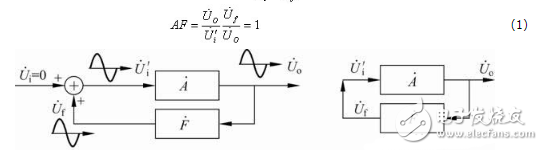
Figure 1 Block diagram of the sine wave oscillator circuit
2. Establishment and stability of sine wave oscillation
The initial signal of an actual sine wave oscillating circuit is caused by disturbances in the internal noise of the circuit and transient processes. Usually the spectrum of these noises and disturbances is very wide and small. In order to finally obtain a stable sinusoidal signal, first, a frequency selective link must be used to select the component of the desired frequency from the noise or disturbance signal to satisfy the phase balance condition, and the other frequency components do not satisfy the phase balance condition. Secondly, in order to enable the oscillation to be established from small to large, it is required to meet
|AF|"1(4)
Equation (4) is called a starting condition for sinusoidal oscillation.
It can be seen from equation (4) that after the oscillation is established, the signal grows from small to large, and a stable sine wave cannot be obtained. In fact, the amplitude of the signal is ultimately limited by the nonlinearity of the amplifier circuit. When the amplitude is gradually increased, |A| will gradually decrease, and finally |AF|=1 reaches the amplitude balance condition, thereby stabilizing the sine wave oscillation. .
3. Composition of sine wave oscillation circuit
It can be seen from the above analysis that the sine wave oscillation circuit must have the following four basic steps in terms of composition.
(1) Amplifying circuit: to ensure that the circuit can be from the start-up to the dynamic balance process, the circuit obtains a certain amplitude output and realizes energy control.
(2) Frequency selection network: Determine the oscillation frequency of the circuit, so that the circuit generates oscillation of a single frequency, that is, the circuit generates sinusoidal oscillation.
(3) Positive feedback network: Introduce positive feedback so that the input signal of the amplifying circuit is equal to the feedback signal.
(4) Stable link: that is, the nonlinear link, the role is to stabilize the output signal amplitude.
In many practical circuits, the frequency selective network and the positive feedback network are often combined into one. Moreover, for discrete component amplifying circuits, there is no additional stabilization link, and the nonlinearity of the transistor characteristics is stabilized. effect.
The sine wave oscillation circuit is often named according to the components used in the frequency selection network, and is classified into three types: an RC sine wave oscillation circuit, an LC sine wave oscillation circuit, and a quartz crystal sine wave oscillation circuit. The RC sine wave oscillation circuit has a low oscillation frequency, generally below 1 MHz; the LC sine wave oscillation circuit has a high oscillation frequency, generally above 1 MHz; the quartz crystal sine wave oscillation circuit can also be equivalent to an LC sine wave oscillation circuit, which is characterized by The oscillation frequency is very stable.
Classic design of oscillating circuitRC oscillator
A circuit composed of RC components is used as a sine wave oscillating circuit of a frequency selective network, which is called an RC oscillator. According to the structural characteristics of the feedback network, the RC oscillator circuit can be divided into an oscillating circuit of RC phase shifting type, RC bridge type and double T type frequency selective network. The RC bridge type oscillation circuit uses the RC series-parallel circuit as the frequency selection network, so it is also called the RC series-parallel oscillation circuit, as shown in Figure 1-29.
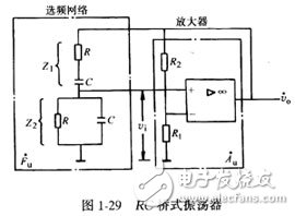
This circuit consists of two parts, the amplifier Au and the frequency selective network Fuo Au is a voltage series negative feedback amplifier composed of integrated operational amplifiers, while the Fu is composed of Zl and Z2, and also serves as a positive feedback network. Zl, Z2 and Rl, R2 form a four-arm bridge. The input and output of the amplifier circuit are respectively connected to the two diagonals of the bridge. Therefore, this RC oscillator circuit is also called RC bridge oscillator.
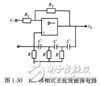
RC phase shift sine wave oscillating circuit
The RC phase shift sine wave oscillating circuit uses the RC phase shifting network as a feedback link of the sine wave oscillating circuit, as shown in Figure l-30. The RC phase shifting network of the oscillating circuit provides a phase shift of 180° solution, and the amplifier uses an inverting input proportional amplifying circuit, so φa=-180. , φa + φf = 0 ° to meet the phase condition of the oscillation, as long as the thermistor Rf is adjusted so that the amplification factor is sufficient to compensate for the signal amplitude attenuation caused by the feedback network, a sinusoidal oscillation signal can be generated.
Transformer feedback LC oscillator
The feedback network uses a transformer, and the primary winding of the transformer is connected in parallel with the capacitor to form an oscillating circuit as a frequency selective network, instead of the transistor collector resistor Rc, the feedback voltage is drawn back from the secondary winding of the transformer and applied to the input end of the amplifying circuit, the circuit As shown in Figure 1-31.
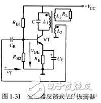
The characteristics of the transformer feedback LC oscillating circuit are that the oscillating frequency is easy to adjust, and it is easy to achieve impedance matching and achieve the requirements for starting vibration. The output waveform is generally low, and the frequency stability is not high. The frequency of generating a sine wave signal is several kilohertz to several tens of megahertz. Suitable for less demanding equipment.
Inductance three-point oscillator
A typical circuit for an inductive three-point oscillator is shown in Figure 1-32. In the LC tank circuit, the inductor has a tap to split the coil into two parts, namely coil L1 and coil L2, the 3 terminal of coil L1 is connected to the base B of the transistor, the 1 terminal of coil L2 is connected to the collector C of the transistor, and the center tap 2 Connect the emitter E. That is to say, the three ends of the inductor are respectively connected to the three poles of the transistor, so it is called an inductor three-point oscillator, also known as a Hartley oscillator.
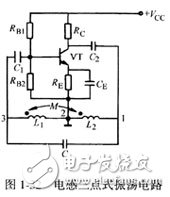
In this circuit, L1 doubles as a feedback network, and the L1 feedback voltage is applied to the input terminal of the transistor through the coupling capacitor C1. After amplification, the high-frequency oscillation signal is obtained in the LC oscillation circuit, as long as the position of the inductor coil is properly selected. By making the feedback signal larger than the input signal, an un-attenuated equal-amplitude oscillation can be obtained in the LC loop.
The oscillation frequency can be obtained by the following formula:

Where L1 and L2 are the self-inductance coefficients on both sides of the coil tap; M is the tile inductance of the two-stage inductor; C is the oscillating capacitor; o is the oscillation frequency.
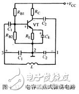
Capacitor three-point oscillator
Figure 1-33 shows a typical circuit diagram of a capacitor three-point oscillator. Its structure is similar to that of an inductive three-point oscillator, except that L and C are interchanged. In the LC oscillation circuit, two capacitors are connected in series to form a capacitor branch. There is a lead-out end between the two capacitors. A part of the voltage is fed from the capacitor branch of the LC tank to the input end of the amplifier circuit through the lead-out terminal. They are connected to the three poles of the transistor, so this circuit is called a three-point LC oscillator, also known as a Colpitts oscillator.
500 puffs disposable vape pen kits are so convenient, portable, and small volume, you just need to take them
out of your pocket and take a puff, feel the cloud of smoke, and the fragrance of fruit surrounding you. It's so great.
We are China's leading manufacturer and supplier of 500 puff disposable vape,500 puff vape pen, 500 puffs vape kit,
500 puffs e-cigarette, disposable vape pen, and e-cigarette kit, and we specialize in Disposable Vapes, e-cigarette vape
pens, e-cigarette kits, etc.
500 puff disposable vape,500 puff vape pen,500 puffs vape kit,disposable vape 500 puffs,vape pen 500 puffs
Ningbo Autrends International Trade Co.,Ltd. , https://www.vapee-cigarettes.com