Microcontroller Unit (MCU), also known as Single Chip Microcomputer or Single Chip Microcomputer, properly reduces the frequency and specifications of the Central Processing Unit (CPU) and stores the memory (memory). Peripheral interfaces such as counters (TImer), USB, A/D conversion, UART, PLC, DMA, and even LCD driver circuits are integrated on a single chip to form a chip-level computer for different combinations of different applications. Such as mobile phones, PC peripherals, remote controls, to automotive electronics, industrial stepper motors, robotic arm control, etc., can be seen in the MCU.
The MCU is connected to the temperature sensor via an I2C bus. The I2C bus occupies two MCU input and output lines, and the communication between the two is completely dependent on software. The address of the temperature sensor can be set via 2 address pins, which allows 8 such sensors to be connected simultaneously on an I2C bus. When an MCU needs to access a sensor, first issue an 8-bit register pointer? Then send the address of the sensor (7-bit address, the low bit is the WR signal). There are three registers in the sensor for the MCU to use. The 8-bit register pointer is used to determine which register the MCU will use. The main program constantly updates the sensor's configuration registers, which causes the sensor to operate in single-step mode, and the temperature is measured every time it is updated.
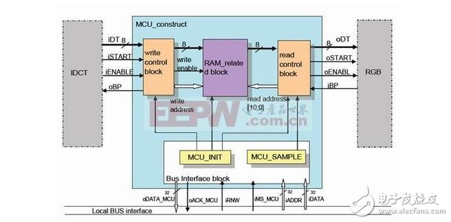
To read the contents of the sensor measurement register, the MCU must first send the sensor address and register pointer. The MCU sends a start signal, then sends the sensor address, then sets the RD/WR pin high to read the measured value register.
In order to read the 16-bit data in the sensor measurement register, the MCU must perform two 8-bit data communication with the sensor. When the sensor is powered up, the default measurement accuracy is 9 bits and the resolution is 0.5 C/LSB (range -128.5 C to 128.5 C). This solution uses the default measurement accuracy. The sensor can be reset as needed to increase the measurement accuracy to 12 bits. If only a general temperature indication, such as a thermostat, is required, then a resolution of 1 C will suffice. In this case, the lower 8 bits of the sensor data can be ignored, and only the high 8 bits of data can be used to achieve the resolution 1 C design requirement. Since the register is read in the order of the first 8 bits and the lower 8 bits, the lower 8 bits of data can be read or not. There are two advantages to reading only the upper 8 bits of data. The first is to shorten the working time of the MCU and the sensor, and reduce the power consumption. The second is that it does not affect the resolution index.
After the MCU reads the measured value of the sensor, it will then convert and display the result on the LCD. The whole process includes: judging the sign of the display result, converting the binary code to the BCD code, and transmitting the data to the relevant register of the LCD.
After the data is processed and the results are displayed, the MCU issues a single-step command to the sensor. A single-step command causes the sensor to initiate a temperature test and then automatically enters standby mode until the analog-to-digital conversion is complete. After the MCU issues a single-step instruction, it enters LPM3 mode. At this time, the MCU system clock continues to work, and a timer interrupt is generated to wake up the CPU. The length of the timing can be adjusted programmatically to suit the needs of the specific application.
The basic structure of the MCU:1. The central processing unit CPU includes an arithmetic unit, a controller, and a register set. It is the core component inside the MCU and consists of two parts: the computing component and the control component. The former can complete the arithmetic logic operation of the data, the bit variable processing and the data transfer operation, and the latter is to coordinate the work at a certain timing, and is a component for analyzing and executing the instructions.
2. Memory, including ROM and RAM. ROM program memory, the work of the MCU is executed in a sequence according to the pre-programmed program. The ROM program memory is used to store the programmed program (the system program is compiled and written by the manufacturer). The stored data does not disappear after power down. The ROM is further divided into on-chip memory and off-chip (extended) memory.
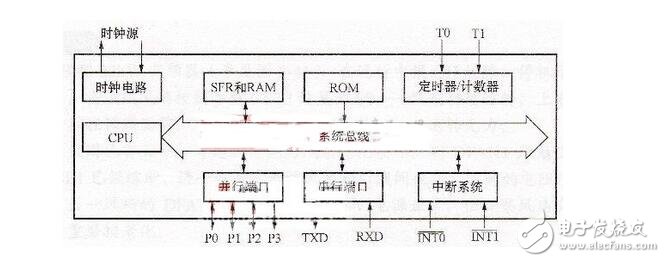
The RAM data memory can write data at any time during the running of the program, and can read the data at any time. Stored data cannot be maintained after power down.
RAM is also divided into on-chip data memory and off-chip (extended) memory.
3. Input and output I/O interfaces are connected to external input and output (circuit) devices. Digital I/O interface such as PO/P1/P2/P3, the internal circuit includes circuit such as port latch, output driver and input buffer. Among them, PO is a three-state bidirectional interface, P1/P2/P3 digital I/O port, and the internal driver is an “open collector†output circuit. When applied, internal or external circuits are connected with pull-up resistors. Each port can be used as a digital signal input or output port, and has a multiplexing function (refer to the port function has a first function, a second function or even several functions, which can be flexibly set in the application).
In addition to the digital I/O port, the MCU device also has an ADC analog input and output port. The input signal is converted into a digital (frequency) signal by an internal A/D conversion circuit, and then processed; for an analog signal, After D/A conversion, it is output to an external circuit.