introduction
DC stabilized power supply is a relatively common electronic device, and has been widely used in many fields such as electronic circuits, experimental teaching, scientific research and so on. In recent years, the development of embedded technology has been extremely rapid, and high-integration processors with microcontrollers and embedded ARM as the core have emerged, and have been widely used in the fields of automation and communication. The power industry has also begun to implement a digitally regulated power supply control system using an embedded controller with rich internal resources. The digital regulated power supply uses pulse width modulation (PWM) to control the turn-on and turn-off of switching devices such as MOS transistors, thereby achieving stable output of voltage and current. The digital regulated power supply also has a self-diagnostic function that enables overvoltage and overcurrent protection and fault warning.
Compared with the previous analog power supply, the digital regulated power supply greatly reduces the errors, aging, temperature drift, non-linearity and other problems that are common in analog power supplies, and improves the flexibility and adaptability of the power supply. Apply SAMSUNG's embedded ARM processor S3C2440 chip to the design of digital power supply for laboratory test system, adopt C language and assembly language, realize an embedded ARM processor as the core, with PID controller and touch screen A functional test system for digitally regulated power supply control systems.
1 Test system digital regulated power supply composition and working principle
The digital regulated power supply consists of a main controller, a PWM voltage regulator circuit, a voltage and current sampling circuit, a PID controller, and a touch screen. The system block diagram is shown in Figure 1.
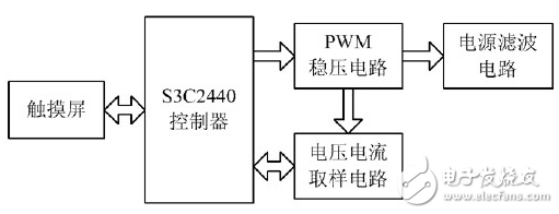
Figure 1 System block diagram
The power supply samples the output voltage and current signals for PID control, and finally outputs the PWM drive waveform to adjust the output voltage. The output voltage is provided to the chip test platform for use in testing the chip.
The front end AC power is input to the rectifier module, and after rectification and filtering, a smooth DC voltage is output. This DC voltage is directly output to the IGBT module.
The high-precision A/D converter converts the voltage and current signals outputted from the back-end into analog digital quantities and supplies them to the S3C2440 for digital PID calculation. After the PID controller operation, the S3C2440 outputs PWM to the IGBT to form a closed-loop control system. The voltage and current are controlled to stabilize the output, thereby realizing the digital regulated power supply design and providing it to the chip test system. The ARM controller implements a human-computer interaction interface through a touch screen, and sets parameters and display information on the touch screen.
2 hardware design
2.1 ARM control system components
In view of the high requirements of PID operation and PWM wave output module, SAMSUNG's S3C2440 is selected through examination. This is a 32-bit CPU based on ARM920T core. It has a frequency of up to 400MHz and can fully meet the real-time requirements of PID controller operation. 16-bit timer for PWM pulse with accuracy up to 0.03μs and dead-end protection; 24 external interrupt sources for real-time response to external fault information; embedded in the LCD controller and own DMA channel, so that the voltage and current values ​​can be displayed on the LCD in real time, and some required parameters can be designed through the touch screen; up to 140 general-purpose I/O ports can easily expand the external interface and equipment; With ADC, 10-bit digital encoding, up to 500kSPS conversion rate, to meet the A / D conversion accuracy required by the test system.
2.2 PWM voltage regulator circuit design
The principle of Pulse Width Modulation (PWM) is that the PWM modulation signal controls the on and off of the semiconductor power switching device, so that the output terminal obtains a pulse with equal amplitude and unequal width, which is stabilized after processing. DC voltage output.
The PWM modulation signal is modulated by the ARM main controller according to the set voltage value, and the pulse width is modulated according to a certain rule.
The PWM regulator circuit is shown in Figure 2.
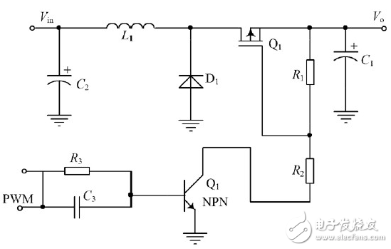
Figure 2 PWM regulator circuit
The switching speed of semiconductor power switching devices directly affects the conversion efficiency and load capacity of the power supply. In the PWM regulator circuit of this system, the driving circuit is composed of resistors, capacitors, transistors and FETs, and the MOSFET is voltage unipolar metal oxide. Silicon field effect transistors require very little drive power and are easy to drive. The input impedance of the MOSFET is very high, and its turn-on and turn-off are equivalent to the input capacitor charging and discharging process. According to the parameters of the selected device, the satisfied conditions are calculated to ensure that the driving circuit provides a sufficiently large overcharge current to realize fast and reliable switching of the MOSFET.
3 software design
Using S3C2440 as the core processor, its rich on-chip resources and excellent computing speed ensure the real-time performance of the system. The writing software mainly uses C language to drive and develop application programs. Its large-capacity memory can fully satisfy the system program. data storage.
The main functions and software implementation methods of the ARM processor in this test system are as follows.
3.1 PWM wave generation
PWM is used to drive the IGBTs in the circuit. The period and pulse width of the output PWM wave are changed according to the output samples, setting and adjusting the values ​​in the timer configuration register TCFGn and the timer n count buffer register TCNTBn. Modifying the value of TCNTBn can control the duty cycle of the PWM wave to increase or decrease by 1. The PWM output duty cycle is increased or decreased by one thousandth, and one thousandth of the control precision can be achieved.
3.2 Monitoring and protection system
In order to enable the digital regulated power supply to reliably and safely supply voltage to the test system, the system is equipped with a monitoring and protection system, mainly for overcurrent protection and overvoltage protection. The ARM processor uses dual detection of voltage and current. When the voltage and current exceed the set dangerous value range, the sound and light alarms and activates the protection circuit.
3.3 PID control algorithm
The PID controller is composed of proportional, integral and differential controllers. The measured controlled object (the voltage and current values ​​in this system) is compared with the set value. This error is used to adjust the response of the system to achieve dynamic real-time. Control process.
In the digital regulated power supply PID control system, the proportional link control voltage and current output is proportional to the input error signal, but there is a steady-state error, that is, the deviation between the actual value and the given value, so it needs to be introduced. The integration step eliminates steady-state errors to improve system accuracy. However, due to the integration of the power system during the turn-on and turn-off, the voltage and current are over-adjusted and even oscillated. In order to reduce the influence of this aspect, a range of error values ​​is set. When the error between the voltage current and the set working value is less than the given value, the integral link is used to eliminate the steady-state error generated by the proportional link of the system. The PID control algorithm sets the threshold ε. When |e(k)| ε, the PD control link is used to reduce the overshoot and make the system have a faster response. When |e(k)| ε, the PID is used. Control to ensure voltage and current accuracy and stability. After the voltage reaches the accuracy range of one thousandth, it is necessary to add the integral link to complete the rapid and stable output when the power is turned on. The PID algorithm flow chart is shown in Figure 3.
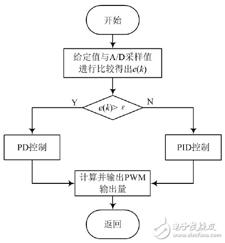
Figure 3 PID control algorithm flow chart
The PID control algorithm program uses the structure definition:
Struct PID{
Unsigned int SetPoint; //Set the target Desired Value
Unsigned int ProporTIon; //proportional constant ProporTIonal Const
Unsigned int Integral; //Integral constant Integral Const
Unsigned int DerivaTIve; //Differential constant Derivative Const
Unsigned int LastError; //Error[-1]
Unsigned int PrevError; //Error[-2]
Unsigned int SumError; //Sums of Errors
}spid;
In the PID control algorithm, the voltage and current output are dynamically controlled while being continuously compared with a given value, while ensuring the accuracy of the voltage and current output.
The PID control algorithm program is as follows:
Unsigned int PIDCalc(struct PID *pp,unsigned int Next-Point)
{
Unsigned int dError, Error;
Error=pp-"SetPoint-NextPoint; //Deviation
Pp-"SumError+= Error; //Points
dError=pp-"LastError-pp-"PrevError; //current differential
Pp-"PrevError=pp-"LastError;
Pp-"LastError= Error;
Return(pp-》Proportion* Error //proportion
+pp-》Integral*pp-》SumError //Integral
+pp-》Derivative*dError); //differential term
}
The overall program flow chart of the test system is shown in Figure 4.

Figure 4 main program flow chart
The test system digital regulated power supply designed in this paper can meet the power requirements required for chip testing. Figure 5 shows the voltage of one output. As can be seen from the figure, the output voltage is stable.
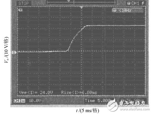
Figure 5 output voltage waveform
4 Conclusion
The regulated voltage supply designed in this paper provides stable and reliable voltage and stable system operation. Due to the large number of scalable I/Os, it is possible to provide a variety of required regulated supply voltage values ​​for multiple chips simultaneously. The system can not only be used in laboratory chip testing, but also can modify some control programs through software programming methods, so that the designed regulated power supply is used as the power supply voltage for intelligent electronic product performance testing, thus improving the efficiency of the device. , has a good application prospects.
We are Manufacturer and Supplier to offer modular plugs in standard configurations to terminate modular cords for patching or work area applications. Our Modular plugs can be terminated to the exact cable length needed in order to maintain a neater, more organized installation. The modular plugs terminate twisted-pair cable with 26 - 22 AWG (0.40mm - 0.64mm) solid or 7-strand conductors with an insulated conductor diameter of 0.86 - 0.99mm (0.034 - 0.039 in.). All modular plug contacts have 50 microinches minimum of gold plating over nickel and meet TIA-968-A and IEC 60603-7 specifications.
Modular Plug is the name given to a family of electrical connectors originally used in telephone wiring and now used for many other purposes. Many applications that originally used a bulkier, more expensive connector have now migrated to modular connectors. Probably the most well known applications of modular connectors are for telephone jacks and for Ethernet jacks, both of which are nearly always Modular Connectors.
Modular Connectors were originally used with the registered jack system, which precisely describes how the connectors are wired for telecommunications. The registered jack specifications define the wiring patterns of the jacks, not the physical dimensions or geometry of the connectors of either gender. Instead, these latter aspects are covered by ISO standard 8877, first used in ISDN systems. TIA/EIA-568 is a standard for data circuits wired on Modular Plug&Connectors.

RJ45 Modular Plugs, RJ11 Modular Plugs, AMP Modular Plugs, Modular Connector, Cat6 Modular Plugs, Cat5e Modular Plugs
NINGBO YULIANG TELECOM MUNICATIONS EQUIPMENT CO.,LTD. , https://www.yltelecom.com