1. Inverter power supply circuit using CD4047 multivibrator
Introduce a low-power inverter power supply with an output power of 30 W, which can be used as a power source for low-power bulbs, energy-saving lamps, and black-and-white TVs in the event of a power outage.
The inverter power supply circuit is composed of a charging circuit, a multivibrator circuit and a power output circuit, as shown in Figure 4-7.
The charging circuit is composed of a power switch S1, a power transformer T1, rectifier diodes VD1 to VD4, a resistor R1, a charging indicating LED VL1 and a filter capacitor C1; the multivibrator circuit is composed of a CMOS multivibrator integrated circuit IC and resistors R2 to R4. The potentiometer RP, the capacitor C2, the diode VD5, the switch S2 and the inverter working indicator light emitting diode VL2 are composed; the power output circuit is composed of the high power field effect transistors VF1, VF2, the resistors R5, R6, the step-up transformer T2 and the capacitor 03.
When charging, switch S1 is turned on, and the voltage of 220 V of AC is first reduced to 12 V by AC through T1, and then rectified by VD1 to VD4 and filtered by C1 to charge battery GB. At the same time, VL1 lights up, indicating that the inverter is charging.
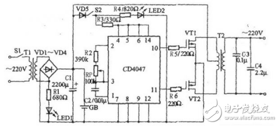
Figure 4-7 Inverter power supply circuit using CD4047 multivibrator
During inverter (s1 should be turned off), the +12 V voltage supplies the operating voltage to VF1 and VF2 via the primary winding of T2. After S2 is turned on, the +12 V voltage supplies the operating voltage to the IC via VD5, S2, and R3, and VL2 is lit, indicating that the inverter is in the inverter state.
After the multivibrator oscillates, two low-frequency oscillating signals of opposite phase and equal amplitude (frequency 50 Hz) are output from pins 10 and 11, respectively, and the signal is amplified by VF1 and VF2 (VF1 and VF2 are alternately turned on) After that, an alternating current of 220 V is generated across the secondary winding (secondary winding) of T2.
In order to increase the output power of the inverter, the capacity of GB and the power of T1 and T2 can be increased, and the field effect transistor is connected in parallel by two tubes.
Adjust the resistance of the RP so that the operating frequency of the multivibrator is 50 Hz.
2. Linear oscillator circuit with CD4047B as the core
This circuit is mainly used as a linear CMOS oscillator circuit. In the circuit diagram, the potentiometer RP and the transistor VT form an adjustment circuit for the relationship between the frequency and the line. The RP can adjust the oscillation frequency of the CD4047B in the range of 1:100, and the emitter resistance R of the VT and the variable base voltage jointly set the collector current. The bridge formed by the diodes VD1 to VD4 ensures symmetric operation in the positive and negative half cycles.
As shown in the figure, it is a linear oscillation circuit diagram based on the monostable trigger/unstable multivibrator CD4047B. This circuit is mainly used as a linear CMOS oscillator circuit.
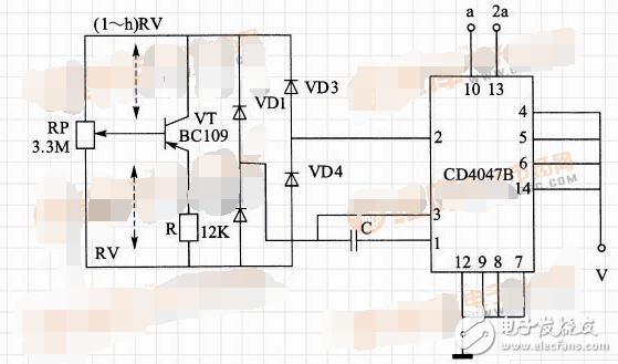
Linear oscillator circuit
In the circuit diagram, the potentiometer RP and the transistor VT form an adjustment circuit for the relationship between the frequency and the line. The RP can adjust the oscillation frequency of the CD4047B in the range of 1:100, and the emitter resistance R of the VT and the variable base voltage jointly set the collector current. The bridge formed by the diodes VD1 to VD4 ensures symmetric operation in the positive and negative half cycles.
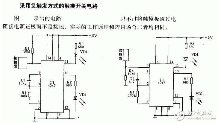
3. Touch switch circuit composed of CD4047
A color filter is an Optical Filter that expresses colors. It can precisely select the small range of light waves to be passed, while reflecting off other undesired wavelengths. The color filter is usually installed in front of the light source, so that the human eye can receive the saturated light of a certain color. There are infrared filters, green, blue, etc. Compared with UV filters and VD filters, it is a general term for colored filters. Such as contrast filter, color separation filter, LB filter, etc.
Colored glass exhibits different colors due to its absorption in the visible light waveband. Colored glass is widely used in laser protection, industrial measurement and environmental measurement instruments.
Black Glass Filter,Red Glass Filter,Yellow Glass Filter,Green Glass Filter
Bohr Optics Co.,Ltd , https://www.bohr-optics.com