1) Pull-up resistor:
1. When the TTL circuit drives the COMS circuit, if the high level of the TTL circuit output is lower than the lowest level of the COMS circuit (generally 3.5V), then the pull-up resistor needs to be connected at the output end of the TTL to improve Output a high value.
2. The OC gate circuit must be connected with a pull-up resistor before it can be used.
3, in order to increase the drive capability of the output pin, some of the microcontroller pins often use pull-up resistors.
4. On the COMS chip, in order to prevent damage caused by static electricity, the unused pins cannot be suspended. Generally, the pull-up resistor is connected to reduce the input impedance and provide a discharge path.
5. The pin of the chip is added with a pull-up resistor to increase the output level, thereby improving the noise margin of the input signal of the chip and enhancing the anti-interference ability.
6. Improve the anti-electromagnetic interference capability of the bus. When the pins are suspended, it is easier to accept external electromagnetic interference.
7. The resistance mismatch in long-line transmission is easy to cause reflected wave interference, and the pull-down resistor is resistance matching, which effectively suppresses reflected wave interference.
2) What is the pull up?
Pull-up is to clamp an indeterminate signal through a resistor at a high level! The resistor acts as a current limiting device at the same time! Pull down the same reason! The pull-up is to inject current into the device and the pull-down is the output current. Weak strength is only the resistance of the pull-up resistor is different, there is no strict distinction. For non-collector (or drain) open-circuit output circuits (such as common gate circuits), the ability to boost current and voltage is limited. The function of the pull-up resistor is mainly to output current channels for open-collector output circuits.
3) Why use a pull resistor:
Generally, when the single button is used for triggering, if the IC itself does not have an internal resistor, in order to maintain the single button in the untriggered state or return to the original state after the trigger, another resistor must be connected outside the IC.
Digital circuits have three states: high, low, and high-impedance. Some applications do not expect a high-impedance state. They can be stabilized by pull-up or pull-down resistors, depending on design requirements. !
Generally speaking, I/O ports, some can be set, some can not be set, some are built-in, some need to be external, the output of I/O port is similar to C of a triode, when C is connected through a resistor and power supply When together, the resistor becomes the upper C-pull resistor, that is, if the port is high when it is normal, and C is connected to the ground through a resistor, the resistor is called a pull-down resistor, so that the port is normally Low level. For example, when a port with a pull-up resistor is set to the input state, its normal state is high, which is used to detect the input of the low level.
Pull-up resistors are used to provide current when the bus drive capability is insufficient. The general term is to draw current, and the pull-down resistor is used to sink current.
4) Weak pull-up
The weak pull-up is generally used for communication with peripheral devices, such as the IIC bus, but not for pull-up applications that require drive capability. When the I/O port is set to the weak pull-up output mode, there is approximately 100K resistor between each I/O port and VDD. If the output logic level is 1, the output has a level close to VDD; if the output is 0, the weak pull-up circuit is automatically turned off. When the output is in the analog input state, the weak pull-up circuit will also automatically turn off.
5) Open drain output
The output is equivalent to the collector of the transistor. A pull-up resistor is required to get a high state. It is suitable for current-type driving, and its ability to absorb current is relatively strong (generally within 20ma).
The "drain" mentioned in the open-drain circuit concept refers to the drain of the MOSFET. Similarly, the "set" of the open circuit refers to the collector of the triode. An open drain circuit is a circuit that uses the drain of a MOSFET as an output. A common use is to add a pull-up resistor to the circuit outside the drain. The complete open drain circuit should consist of an open-drain device and an open-drain pull-up resistor.
6) The circuit that forms the open-drain form has the following characteristics:
1. Reduce the drive inside the IC by using the drive capability of the external circuit. When the internal MOSFET of the IC is turned on, the drive current flows from the external VCC through R pull-up and the MOSFET to GND. Only a very low gate drive current is required inside the IC. Figure 1.
2. Pins of multiple open-drain outputs can be connected to one line. Form a "logical" relationship. When any of PIN_A, PIN_B, and PIN_C goes low, the logic on the open drain line is 0. This is also the principle that I2C, SMBus and other buses determine the bus occupancy status.
3. The transfer level can be changed by changing the voltage of the pull-up power supply. The logic level of the IC is determined by the power supply Vcc1, while the output high level is determined by Vcc2. This way we can control the output high logic with low logic.
4. Open-drain Pin is not connected to the external pull-up resistor, it can only output low level (so for the classic 51 single-chip P0 port, to do the input and output function must add external pull-up resistor, otherwise it can not output high Level logic).
5. Standard open drain feet generally have only the ability to output. Add other judgment circuits to have the ability to input and output in both directions.
7) Pay attention to the application:
1. The principle of open drain and open set is similar. In many applications, we use open collector circuits instead of open drain circuits. For example, an input Pin is required to be driven by an open drain circuit. Then our common driving method is to use a triode to form an open circuit to drive it, which is convenient and cost-effective.
2. The value of the pull-up resistor R pull-up determines the speed of the edge of the logic level transition. The larger the resistance, the lower the speed and the lower the power consumption. vice versa.
The Push-Pull output is the so-called push-pull output. It should be more suitable than the CMOS output in the CMOS circuit. It should be impossible to do the push-pull output capability in CMOS. Output capacity See the area of ​​the IC's internal output pole N tube P tube. Compared with the open-drain output, the high-low level of push-pull is low by the power supply of the IC, and it is not easy to do logic operations. Push-pull is the most widely used output stage design in CMOS circuits.
The I/O port of 51 MCU is open-drain output, and the driving ability is weak. Therefore, it is generally necessary to add a pull-resistor to drive the next-level circuit. The AVR and STM8S series are all true bidirectional I/O ports, push-pull. Output, current up to 20mA.
Second, push-pull (Push-Pull) output:Generally speaking, the two triodes are controlled by two complementary signals, and the other triode is always turned off when one transistor is turned on, which just forms a push-pull connection. Such circuits are also known as push-pull or Totem-pole circuits. The push-pull circuit is suitable for low voltage and high current applications and is widely used in switching power supplies and power amplifier circuits. The simplified circuit diagram is as follows:
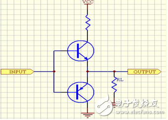
Simple understanding: the structure of the push-pull output is to replace the upper pull-up resistor with a switch. When the output is high, the upper switch is turned on and the lower switch is turned off. When the low level is output, the opposite is true. Compared with OC or OD, such push-pull structure is high and low-level drive capability is very strong. If the two output outputs of different levels are connected together, a large current will be generated, and the output port may be burned out. The OC or OD output mentioned above does not have such a situation because the current supplied by the pull-up resistor is relatively small. If the push-pull output is to be set to a high-impedance state, both switches must be disconnected at the same time (or a transfer gate is used on the output port) so that it can be used as an input state.
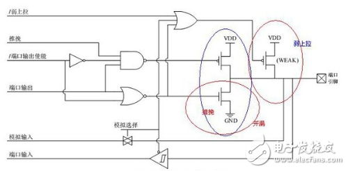
Third, the difference between the weak pull-up output and the push-pull output of the single-chip microcomputerThe difference between this is mainly the size of the driving capability, that is, the output impedance, and the weak pull-up output impedance is large. When there is a large load, the internal resistance of a battery is large, causing the internal resistance to be too large to drive a large one. Load; push-pull output is a push-pull circuit composed of two transistors or FETs (used in analog circuits, such as power amplifier drive motor drive, etc.), this circuit is characterized by small output resistance, so it can drive large The load allows the microcontroller pins to directly drive LEDs, buzzers, and even smaller impedance loads!
Specific circuit can refer to the picture below
Glass Plate Type Liquid Level Gauge Self-closing Valve Body
Glass plate type liquid level gauge self-closing valve body,liquid level gauge self-closing valve body,self-closing valve body,liquid level gauge self-closing valve body price
Taizhou Jiabo Instrument Technology Co., Ltd. , https://www.jbcbyq.com