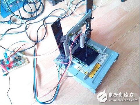
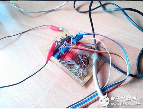
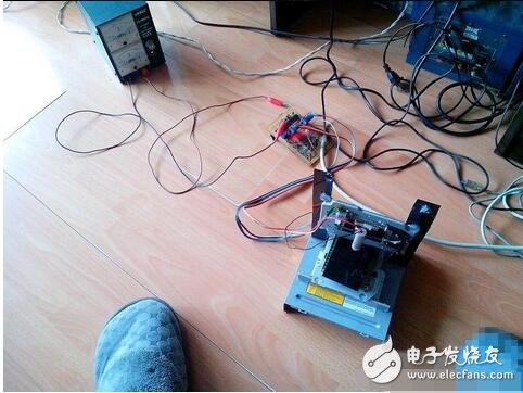
Some people use the laser engraving machine made of waste optical drive, I don't understand their driver board, I only know some things of 51 MCU, so the material at hand begins, first the schematic of the driver board
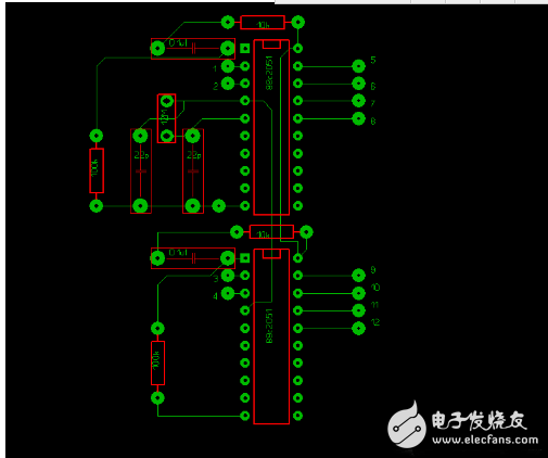
The pins 1 and 3 marked on the driver board are connected to the 2, 3 pins of the parallel port of the computer as stepping drive signals.
The 2, 4 pins marked on the driver board are connected to the 6 and 7 feet of the parallel port of the computer as the step direction signal.
The 5, 6, 7 and 8 pins marked on the drive board are connected to the motor drive board to control one step of the stepper motor, and the 9, 10, 11 and 12 feet are connected to the motor drive board to control the step motor of the other axis.
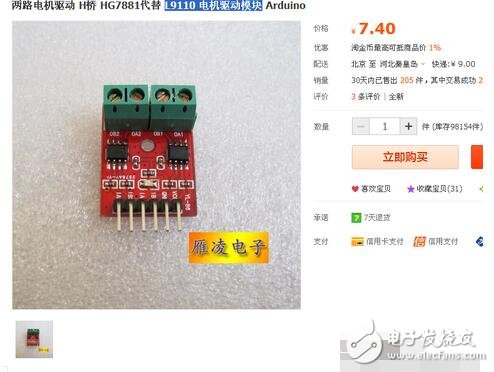
The motor drive board is the L9110 motor drive module bought from Taobao.
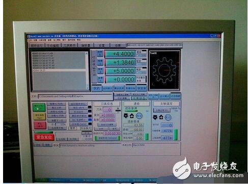
The engraving software I used was Mach3, and the control software was written in C51.
Passing on the control software is very simple.
#include "at89x52.h"
Void main(void)
{
Unsigned int X[8] = {160,32,96,64,80,16,144,128 };//"Define the stepper motor array"
Unsigned char a=0 ; // "Define the array subscript variable, the variable must be a character variable!"
Unsigned int b; // "Define variables and assign values"
P3_1=1;
P3_0=1; // "Make sure P3.1 P3.0 is the accepted signal mode, P should be capitalized!"
While (1)
{
Do
{
;
} while (P3_0==0); // "Confirm whether there is a high level signal"
For( [s:9]3_0==1; ); //"Judge whether it is a stepping pulse signal"
If (P3_1==1) // "Determine the forward signal and perform the forward rotation"
{ P1=X[a];
If(a"7) a++ ;
Else a=0;
}
Else if (P3_1==0) // "Confirm reverse signal, perform reverse"
{ if(a)0) a-- ;
Else a=7;
P1=X[a];
}
For (b=0; b "750; b++); / / "delay"
P1=0;
}
}
CCTV Bracket, CCTV Camera Bracket,CCTV Camera Mounts,CCTV Security Camera Mounting Bracket
Chinasky Electronics Co., Ltd. , https://www.chinacctvproducts.com