In a multi-channel design, driving each channel independently consumes more power, more components, and takes up more board space. As a result, temperature-dependent design is complicated, and sound quality and reliability are lower at higher cost.
This article refers to the address: http://
Therefore, to minimize the power consumption of high-performance multichannel audio systems and simplify associated temperature management, design engineers have long sought high-efficiency Class-D audio amplifiers that provide over 90% efficiency over a wide range of output power levels. In contrast, the traditional Class AB amplifiers used in this market are only about 50% efficient, and the efficiency drops rapidly as the output power level drops. Similarly, engineers are constantly researching the performance of integrated ICs to reduce component count and board area.
Whether in the automotive entertainment or home theater systems market, consumers are always demanding more channels and speakers, each channel being able to handle higher audio power levels. In addition to higher wattages, audiophiles continue to demand improved sound quality, reduced distortion and noise, and excellent isolation between channels.
4-channel driver
Based on this demand, International Rectifier (IR) has combined advanced DirectFET power MOSFETs with innovative integrated audio drivers to develop a 4-channel Class D audio amplifier design that rivals single-channel solutions. To achieve this goal, the circuit uses an integrated audio driver, the IRS2093M, which integrates the channels of four high-voltage power MOSFET drivers onto the same chip. In addition, this 200V device includes an on-chip error amplifier, analog PWM modulator, programmable preset dead time, and reliable protection for a Class D audio amplifier application in a half-bridge topology (Figure 1). In addition to preventing shoot-through current and current surges in the power MOSFET, the programmable preset dead time also enables a scalable power design with power and channel count. These protection features include overcurrent protection (OCP) and undervoltage lockout (UVLO) protection with automatic reset control.
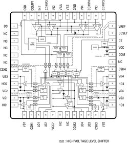
Figure 1: This 200V device integrates four channels of a high-voltage power MOSFETS driver on the same chip. It also features an on-chip error amplifier, analog PWM modulator, programmable preset dead time, and advanced protection.
To achieve best-in-class isolation between different channels, the audio driver deploys proven high-voltage junction isolation technology and a floating gate driver using the Gen 5 HVIC process. This achieves good internal signal isolation on the die, which allows the circuit to process more channels simultaneously, keeping the fundamental noise of each channel at a very low level while minimizing the channel-to-channel Crosstalk.
Next, we constructed a 4-channel half-bridge Class D audio amplifier circuit as shown in Figure 2. It combines an integrated Class D audio controller with a gate driver IRS2093M with eight IRF6665 DirectFET power MOSFETs and several passives. Device. Each channel of the multichannel audio amplifier is designed to provide 120W of output power. For ease of use, this circuit contains all the necessary internal management power.
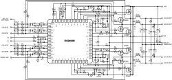
Figure 2: This 4-channel half-bridge Class D audio amplifier is designed with an integrated Class D audio controller and IRS2093M gate driver, as well as eight IRF6665 DirectFET MOSFETs and some passive components.
For optimum overall performance, the IRF6665 power MOSFET is optimized for Class D amplifier designs. In addition to providing low on-state resistance, power MOSFETs have been improved to achieve minimum gate charge, minimum body diode reverse recovery, and minimum internal gate resistance. In addition, DirectFET packages offer lower parasitic inductance and resistance than traditional wire bond packages. Simply put, the optimized IRF6665 MOSFET provides high efficiency and low total harmonic distortion (THD) as well as electromagnetic interference (EMI).
Features and functions
To provide the highest performance and reliable design in a smaller space, this 4-channel Class D audio amplifier solution uses self-oscillating PWM modulation. Since this topology is equivalent to an analog second-order sigma-delta modulation, and the class D switch stage is in the ring, the error in the audible frequency range is shifted to the inaudible frequency according to its operating characteristics, thereby reducing the noise. At the same time, sigma-delta modulation allows designers to perform enough error correction to further reduce noise and distortion.
As shown in Figure 2, the self-oscillating topology combines a front-end integrator, a PWM comparator, a level shifter, a gate driver, and an output low-pass filter (LPF). Although this design can switch at a higher frequency, for some reason it still uses 400kHz as the optimum switching frequency. First, at lower frequencies, the efficiency of the MOSFET is improved, but the inductor ripple current rises and the leakage of the output PWM switching carrier increases. Second, at higher frequencies, switching losses reduce efficiency, but have the opportunity to achieve wider bandwidths. When the inductor ripple current is reduced, the iron loss will rise.
Since in the class D audio amplifier, the direction of the load current changes with the audio input signal, and the overcurrent condition may occur in a positive current period or a negative current period. Therefore, to protect both the high-side and low-side MOSFETs from overcurrent in both directions, programmable overcurrent protection (OCP) provides bidirectional protection with the RDS(on) of the output MOSFET as the current sense resistor. In this design, when the measured current exceeds a preset threshold, the OCP logic outputs a signal to the protection circuit, forcing the HO and LO pins to a low level, thereby protecting the MOSFET from damage.
Due to the structural limitations of high voltage ICs, the current sensing deployment of the high side and low side MOSFETs is not the same. For example, low-side current sensing is based on the VDS across the low-side MOSFET in the on-state state of the device. To prevent the transient overshoot from triggering the OCP, add a blanking interval after the LO is turned on to stop the 450ns overcurrent detection.
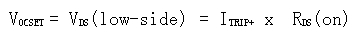
The threshold voltage for low-side overcurrent sensing is set by the OCSET pin and ranges from 0.5V to 5.0V. If the VDS measured for the low-side MOSFET exceeds the voltage of COM corresponding to the OCSET pin, the driver circuit performs the OCP protection procedure. To set the shutdown level of the overcurrent, you can use the following formula to calculate the voltage of the OCSET pin:
To minimize the effects of the input bias current on the OCSET pin, we chose resistor values ​​R4 and R5 to allow the current through the divider to reach 0.5mA or more. At the same time, VREF is input to OCSET through a resistor divider, which improves the immunity to fluctuations in the supply voltage Vcc.
Similarly, for positive load currents, the high-side overcurrent sensing also monitors the load condition, which is monitored based on the VDS measured across the MOSFET during the high-side turn-on of the CSH and Vs pins. When the load current exceeds the preset shutdown level, the OCP protection stops the switch. To prevent transient overshoot from triggering OCP, a blanking interval can be added after the HO is turned on to stop the 450ns overcurrent detection.
Unlike low-side current sensing, the critical value of the CSH pin is internally fixed at 1.2V. However, an external resistor divider R2 and R3 can be used to set a higher threshold. Either way, the external blocking diode D1 is used to block the high voltage from flowing to the CSH pin in the case of a high side open circuit. Based on a 0.6V forward voltage drop across D1, the minimum threshold for high side overcurrent protection is 0.6V.
In short, the critical value VCSH of the CSH pin can be calculated using the following formula:
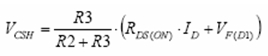
The ID in the equation is the leakage current, and VF(D1) is the forward voltage drop of D1. In addition, the reverse blocking diode D1 is forward biased via a 10 kΩ resistor R1.
To prevent shoot-through or overshoot current from passing through the two MOSFETs, we insert a choke period called dead time between high side turn-off and low side turn-on, or low side turn-off and high side turn-on. The integrated driver allows the designer to optimize performance by selecting a suitable deadband from a range of preset values ​​based on the size of the selected MOSFET. In fact, only two external resistors are needed to set the dead time through the DT pin of the IRS2093. This eliminates the need for external gate timing adjustments and also prevents external noise introduced by adjusting the timing of the switches, which is important to ensure sound performance.
The user must consider the fall time of the MOSFET when determining the optimum dead time. This is because, for practical applications, due to the fall time tf of the switch, the true effective dead time is different from that provided by the data. This means that to determine the effective dead time, the fall time of the MOSFET gate voltage is subtracted from the dead time value in the data sheet.
Similarly, in terms of UVLO protection, the driver monitors the state of voltages VAA and VCC before normal operation begins to ensure that both voltages are above their respective thresholds. If VAA or VCC is below the UVLO threshold, the IRS2093's protection logic turns off LO and HO. As a result, the power MOSFET will cease to operate until VAA and VCC exceed their UVLO thresholds.
In addition, for optimal sound quality, the 4-channel audio board design minimizes line impedance and mutual coupling between the analog and switch sections and ensures that the analog signal is separated from the switch stage and power ground.
Measured performance
We measure the efficiency, total harmonic distortion plus noise (THD+N) and EMI performance of each channel with a sinusoidal signal frequency of 1 kHz, 1 Vrms, and 4 Ω load impedance. In addition, we measured the 4-channel Class D audio amplifier design shown in Figure 2, showing its superior isolation and crosstalk performance. The relevant circuit version has a supply voltage of ±35V and a natural frequency of 400kHz.
As shown in Figure 3, with a 4Ω load and a power output below 50W to 120W, the efficiency per channel is approximately 90%. The main factors contributing to high channel efficiency include the DirectFET MOSFET IRF6665, which produces low on-state and switching losses. At the same time, because the integrated driver provides a safe dead time, there is no cross conduction in the design.
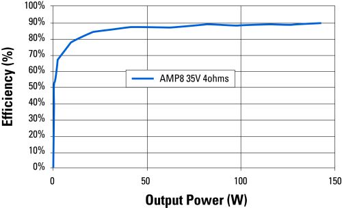
Figure 3: The power output is increased from less than 50W output to 120W at 4Ω load, and the measured efficiency curve shows an efficiency of approximately 90% per channel.
This high efficiency allows the 4-channel design to handle one-eighth of the continuous power rating, which is the normal working environment required for general safety, without the need for any additional heat sink or forced air cooling.
Similarly, tests for distortion have shown that the THD+N performance of each channel is the same across a wide range of output powers. As shown in Figure 4, THD+N will be less than 0.01% when each channel is below 50W and will increase as the output power increases. For example, when the output of each channel is about 100W, the degree of distortion will rise to 0.02%. This performance is consistent over the entire 20Hz to 20kHz audio range, even if the output power is increased from 10W per channel to 50W (under 4Ω load). As shown in Figure 5, the fundamental noise of each channel is maintained below -80 dBv over the entire audio range. The noise is measured at no signal input and at a natural frequency of 400 kHz.
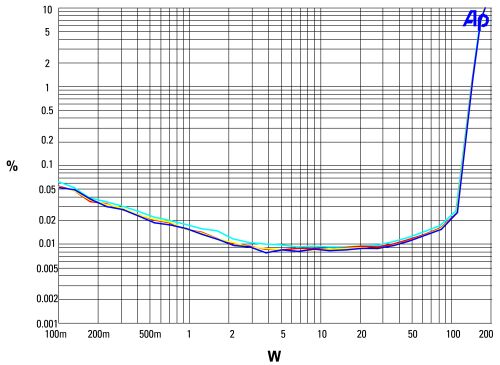
Figure 4: When each channel is below 50W, the total harmonic distortion plus noise (THD+N) will be less than 0.01% and will start to increase as the output power rises.
Similar tests for channel isolation have shown that crosstalk between channels 1 and 3, as well as between channels 1 and 4, is better than -70 dB over the entire audio range with an output power of 60 W per channel.
At the same time, the design provides a good power supply rejection ratio (PSRR) of -68dB at a 1kHz signal frequency. The high PSRR is derived from the natural frequency of the drive. This allows 4-channel Class D amplifiers to deliver superior performance even with unregulated power supplies.
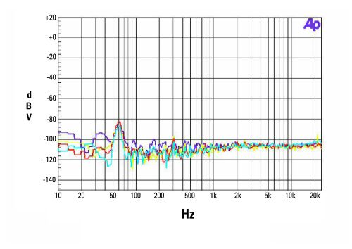
Figure 5: When there is no signal input, the fundamental noise of each channel remains below -80dBv over the entire audio range.
Summary of this article
The 4-channel Class-D audio amplifier solution with the IRS2093M integrated driver delivers efficiency, THD+N and EMI performance comparable to single-channel designs. In addition, the fundamental noise is maintained below -80 dBv over the entire audible range. At the same time, there is excellent isolation between the channels to maintain intermodulation distortion (IMD) at a minimum to provide the desired sound performance. With high efficiency eliminating the need for heat sinks, the integrated audio driver successfully achieved a 4-channel Class D audio amplifier solution with half the footprint.
Led Fish Tank Lights With Remote ADVANTAGE
1. Light using CREE LED chips.
2. Unique technology of Standard module design.
3. Brand new idea,all-round LED optic lens.
4. Increases 15% of the growth.
5. Air-circulation system designed to improve The plants' photosynthesis and growth.
6. Easy Disassembling and Reassembling .
7. Exclusive Design:Checking and indicating defects Automatically.
8. Grow your corals under LEDs
9. Enhance the colors on your fish
Our Led Fish Tank Lights With Remote is popular in led market,cause its elegant outlook and its high quality and competitive price.
Item Display


Key Features
1.The lifespan is over 50000 hours,low maintenance costs.
2.Energy conservation,saving over 80% energy than the traditional HPS.
3.High light efficiency,90% of the light will be absorbed by the aquatic plants,while just 8%-10% to the HPS.
4.Build-in cooling system,could solve the heat dissipation excellently.
5.Built-in power supply, CE approved, No setup required, just simpler and safer plugs directly into AC85V-264V, no reflector & ballast needed.

Convenient in using lights at the same time.

Package Include
1 X Free Hanging Kit
1X Free Power Cord


Quality Control systems and after-sales

All the lamps have passed strict quality examination and are packed carefully before shipping.In order that our customers get high quality lamps,we attach importance to every details.
Application
1. coral reef lighting,fish tank lighting,coral reef tank lighting
2. Aquarium Lighting ,aquarium art,aquarium shop,aquarim centre
3. fish bowl lighting,fish lighting,freshwater lighting,saltwater lighting

Our Company


Philizon enjoys a high reputation in grow led lamp and LED Aquarium Light fields throughout Europe and America,Philizon also insists on taking high technology to design the newest&best Led Grow Light and Aquarium Light constantly as the market request. Our R&D team with more than 10 people has rich experience in appearance design, electronic structure,heat dissipation simulation analysis,optical lens design,light control system etc.Most of our hydroponics full spectrum Led Grow Lighting and Led Fish Tank Lights With Remote are private modules,we have 10 more design patent and utility model patent till now.
Trade Terms
Payment: T/T, L/C, Paypal, 30% deposits before production, 70% balance to be paid before deliverying(Western Union are welcome)
Sample will be delivered within 7 working days.
Discounts are offered based on order quanlityes.
MOQ:sample order are acceptable
Delivery ways:DHL,UPS,FedEx,TNT, door to door,by sea,by air,etc.
Our products ranges:
LED plant grow lights for agricultural lighting;
LED aquarium lights for fish tanks,corals,saltwater tank,marine tank with reef,coral,sps,lps,fish,etc;
Warmly welcome to take a visit on our factory at any time and we will pick you up at the airport in Shenzhen.
Led Fish Tank Lights With Remote
Dimmable Led Aquarium Light,Dimmable Aquarium Light,Coral Reef Led Aquarium Light,Dimmable Aquarium Light Led
Shenzhen Phlizon Technology Co.,Ltd. , http://www.philizon.com