Electromagnetic compatibility (EMC) is an important technical indicator in electronic products. This article describes the main factors, test methods, and criteria that affect solid state relay (SSR) EMC. At the same time, it puts forward the precautions in the test and gives a set of practical results.
1 Introduction
Factors affecting the solid state relay (SSR) electromagnetic compatibility (EMC) are manifold, such as device selection and matching, circuit principles, PCB layout and structure, and so on. Among them, the influence of AC optocouplers (optocouplers) on EMC parameters is often ignored. The main reason is that they have less understanding of their application environment and requirements, and they do not understand EMC standards, equipment usage and test methods. Therefore, when using poor performance devices and unreasonable structures, the EMC performance of solid state relays often does not meet international standards (such as CE, etc.).
2 EMC standard for solid state relays
Electromagnetic compatibility includes electromagnetic radiation (Emission) and electromagnetic immunity (Immunity). For the device, European customers do not require electromagnetic testing (except for individual customers with special requirements), and usually only require testing according to EN50082-2, 1995V EN61000-6-2. But the most important is to test ESD (EN61000-4-2); EFT/B (EN61000-4-4) and SURGE (EN61000-4-5). It should be noted that if the customer requests to test electromagnetic radiation, it should be tested according to EN50081-2 standard, 2001V EN61000-6-4. This paper only tests and generalizes the electromagnetic immunity of SSR. In many years of communication with European customers, we have the following requirements:
(1) EMC is required to test the electromagnetic immunity of the general standard, namely ESD, EFT/B and Surge mentioned above. The voltage levels are 4kV contact discharge and 8kV air discharge, 1kV/5kHz fast group pulse perturbation and 2k V surge shock, and other requirements are not required;
(2) EMC is required to make the universal standard electromagnetic interference immunity up to level 3 test, ie ESD and Surge are the same as above, and EFT/B is required to reach 3kV/5kHz;
(3) Special requirements: ESD requires 6kV/10kV and EFT/B is 4kV
(4) Other requirements: In addition to electromagnetic immunity (Immunity), electromagnetic radiation (Emission) test is also required.
3. Main factors affecting EMC of solid state relays
In order to identify the main factors and combinations that affect the solid state relay EMC, it is necessary to understand the circuit principles that make up the SSR. We have integrated the circuits of major manufacturers in SSR at home and abroad, and have obtained the following common circuit structures using AC optocoupler solutions. These different circuit structures and the same circuit structure were tested using different device combinations to find different EMC performance.
3.1 Circuit principle
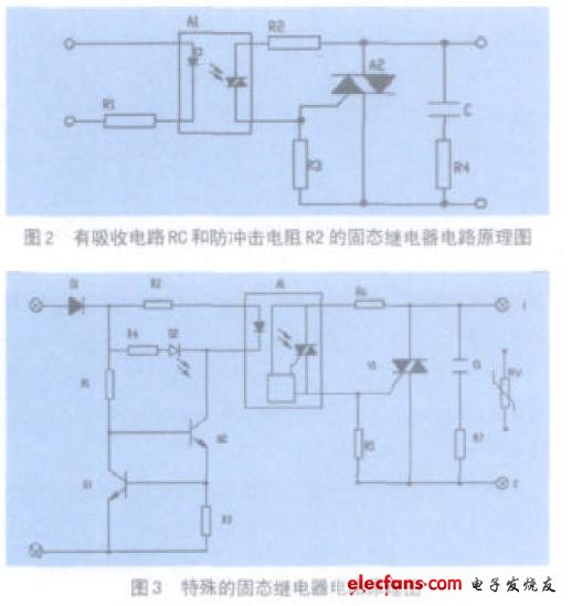
The three circuits of Figure 1, Figure 2 and Figure 3 all implement the functions of a solid state relay. Figure 1 is the simplest circuit schematic of a solid state relay. In the figure, A1 is an AC photocoupler and A 2 is a bidirectional thyristor. Commonly used in small SSRs, users often add devices outside to improve performance. Figure 2 shows the addition of the RC snubber circuit and the anti-shock resistor R2 to Figure 1. R 2 is a protection optocoupler that suppresses the inrush current flowing through the optocoupler at the moment of conduction. The addition of these devices greatly improves the EMC characteristics of the SSR and the surge performance of the surge on the optocoupler. Therefore, this circuit is often used in high reliability applications. Figure 3 is a special circuit that is commonly used in SSR designs with high reliability and high EMC ratings. Diode D1 in the figure prevents input polarity. The constant current circuit is composed of Q1, Q2, R1 and R3 to ensure that the current of the optocoupler A 1 is constant when the input voltage changes. The functions of the RC circuits C 1 , R 7 and R 6 are the same as those of FIG. 2 . The circuit also adds a varistor RV. RV not only enhances the overvoltage protection of the SSR, but also greatly improves its EMC performance.

The following tests were carried out according to the above three different circuits and different structures:
Seucrity Patrol Drone,Rescure Drone with Searching Light, Bouy Drop Drone ,Wireless Megaphone Drones
Seucrity Patrol Drone,Rescure Drone with Searching Light, Bouy Drop Drone ,Realtime Video Drone
shenzhen GC Electronics Co.,Ltd. , https://www.jmrdrone.com