The micro-parts fabricated by MEMS (Micro Electro Mechanical System) technology have the advantages of high precision, reliable action and strong anti-interference ability [1], and large-scale production and processing of micro-parts requires fast and accurate measurement of their two-dimensional size. And the detection equipment is cheaper, that is, online detection. However, existing test methods or instruments have problems such as high price, easy to be disturbed by the outside world, and slow test speed, such as scanning confocal microscope [2], atomic force microscope [2], white light interferometry [3], etc., so they only It is suitable for the occasions where the measurement accuracy is high and the measurement time is not required when it is scientific research, and it cannot meet the requirements of the on-line inspection of micro-parts manufacturers. In recent years, with the wide application of computer vision, many scholars have proposed a method for detecting the two-dimensional size of micro-parts. As in the literature [4-5], a set of detection systems is proposed, and sub-pixel edges are obtained by median filtering, threshold segmentation, sobel edge detection operator and fitting method; similar detection systems are also proposed in [6-7]. The polynomial regression model of the edge transition region is established by the fitting method, and the sub-pixel edge is obtained by the derivation method. However, the fitting method greatly reduces the sub-pixel edge detection speed, especially in the case of high image resolution and more edge points, which can not meet the requirements of fast detection. This paper presents an on-line detection method for two-dimensional dimensions of micro-parts based on industrial cameras.
1 The basis of the online detection method
1.1 Projection transformation principle
The geometric model and relationship mapped from a three-dimensional scene to a two-dimensional image depends on the projection transformation, also known as the imaging transformation. In the simplest case, the geometric model of the imaging process is shown in Figure 1. The spatial points (X, Y, Z) are transformed into points (x, y) of the image plane by projection. Let the image plane in the camera coordinate system xyz coincide with the xy plane and the optical axis along the z-axis. Thus the center of the image plane is at the origin, the coordinates of the center of the lens are (0, 0, λ), and λ is the focal length of the lens [8].
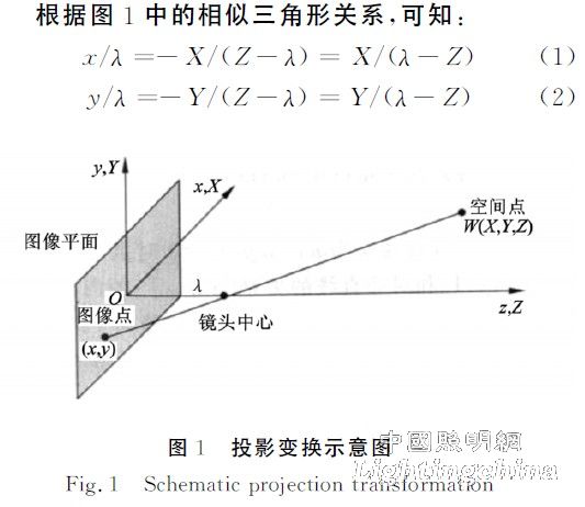
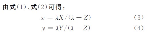
Let a plane α be parallel to the image plane, and the distance between the two planes is Z, then the two points (X1, Y1, Z) and (X2, Y2, Z) on the α plane and the corresponding mapping points in the image plane ( X1, y1) and (x2, y2) have the following relationship:
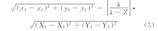
Equation (5) illustrates that the length of a line segment on a plane parallel to the image plane is linear with the length of the corresponding line segment on the image plane. Therefore, when measuring, the optical axis of the lens should be perpendicular to the surface of the object to be measured, so that the actual two-dimensional size of the measured object and the two-dimensional size of the measured object in the image are linear, and the coefficients can pass. Obtained from the measurement of the standard object, from which the measured object, ie the two-dimensional size of the micro-part, can be measured.
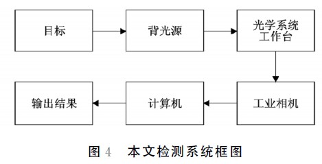
1.2 In the past, the two-dimensional image detection method of micro-parts was introduced. Since the light obtained by the optical system is the target and background reflected light and scattered light, the image will inevitably introduce a certain noise. In addition to the noise generated by the image during generation, transmission and transformation, the literature [4] needs to preprocess the original image with median filtering to reduce the noise of the image. Therefore, this paper improves the detection system of [4], replacing the background of large contrast with LED (light emitting diode). The backlight refers to the light source placed on the back of the object to be tested, as shown in FIG. The object to be tested is illuminated by the backlight to make the edges of the light-transmitting and opaque portions clear, and the optical system obtains the direct light obtained from the backlight, so that the obtained image noise is less and the edge of the object to be tested is relatively clear.

In this paper, an industrial camera (internal integrated image acquisition card) with high image stability, high transmission capability and high anti-interference ability can also greatly reduce image noise, but the price is significantly reduced. The optical system, that is, the optical lens has a maximum magnification of 4.5 times, and the industrial camera has a sensitive surface size of 6.66 mm × 5.32 mm. Suppose an object has exactly 4.5 times magnification and then occupies all the pixels of the sensitive surface. At this time, the resolution of the detection system is 1.156 μm/pixel. The Zernike moment used in this paper is ideally subpixel edge positioning accuracy of 0.1pixel [9], so the maximum resolution of the detection system in this paper is 0.115 6μm.
In this paper, the fast sub-pixel edge detection algorithm proposed in [10] is used to process the image. The detection algorithm uses Zernike moments for sub-pixel positioning. Compared with the fitting method in [4], the Zernike moment has a small calculation amount and a fast processing speed, but its positioning accuracy is lower than the fitting method. Therefore, the detection algorithm can achieve fast sub-pixel positioning of the edge of the micro-part image.
3 Experimental verification
Table 1 is the performance comparison between the detection system and the optical profiler WKYO NT1100 produced by Veeco. It can be seen that the detection system has the characteristics of fast, cheap and high resolution. Therefore, the detection system of this paper is suitable for the two-dimensional size of micro-parts. Online detection.

Fig. 6 shows the obtained micro-part image on the reticle and the result of the processing thereof. The reason for using the reticle is that the reticle in the MEMS processing has high precision with an error range of ± 2 μm. Therefore, the measurement accuracy of the detection system is measured by the micro-part design size of the mask.
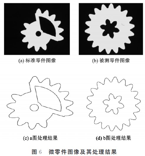
Firstly, the coefficient described above is obtained by using FIG. 6(a) as a standard object, that is, the actual size represented by each pixel in the image, and the radius of the tip circle of the detection and control journal of FIG. 6(c) is the standard size. Calculated by the circle fitting method, the obtained coefficient is 1.964 5μm/pixel; then, by Fig. 6(d), the partial two-dimensional size of the micro-parts of Fig. 6(b) is calculated by the circle fitting method and the coefficient. The results are shown in Table 2. Shown.
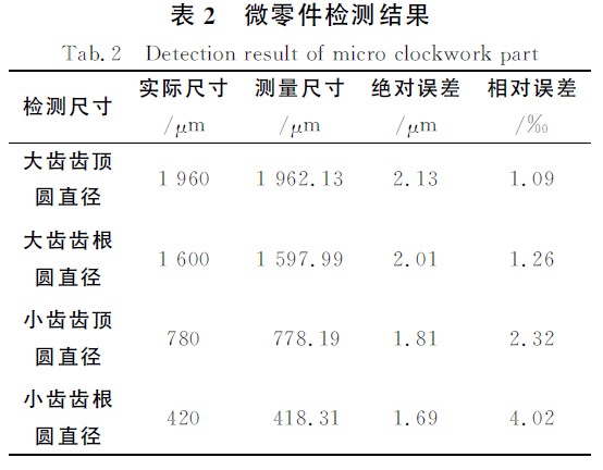
It can be obtained from Table 2 that for the four typical dimensions of the tested parts, the mean absolute error of the system is 1.91 μm and the mean square error is 0.2 μm; the mean error is 2.17 ‰, and the mean square error is 1.35 ‰. The error caused by the radial distortion of the optical lens during projection transformation and the sub-pixel edge positioning error are the main factors causing the measurement error. Since it is not the focus of this paper, it will not be discussed here. The relevant discussion can refer to the literature [9 , 11].
4 Conclusion
This paper presents a method for on-line detection of two-dimensional dimensions of micro-parts. The method is based on a detection system consisting of an LED backlight, an optical lens, a stand, an industrial camera, and a computer. In the measurement, the actual size of each pixel represented by the camera is first calibrated, and then the image of the micro-part is obtained by the detection system. Finally, the image is processed by a fast sub-pixel edge detection algorithm to obtain the two-dimensional size of the micro-part. Experiments show that the method has higher measurement accuracy and faster measurement speed. Therefore, the method can be applied to on-line detection of microscopic two-dimensional dimensions of parts.
Telescopic Antenna description
Telescopic antenna , the portable digital television specialists, is designed specifically for digital reception. With a standard coaxial connection, it can be easily used with almost any portable or living room television set.
Small, compact and lightweight, it is perfect for portable TVs and USB TV tuners; you can easily carry it in your laptop bag or TV case without worrying about extra weight or space. Its magnetic base attaches to large metal objects, using their surface area to enhance the reception quality.
Capable of receiving frequencies of VHF 174-230MHz and UHF 470-862MHz it is ideal for both Digital ATSC and DAB broadcasting.
Telescopic Antenna Specification
Electrical Specifications
Frequency Range (MHz): 470-862MHz
Input Impedance (Ω): 50
V.S.W.R:≤1.2
Gain (dBi): 3dBi
F/B Ratio: ≥15dB
Horizontal Beam width: 60°-90°
Vertical Beam width: 70°-70°
Polarization Type: Vertical
Power Capacity (w): 100
Picture show


Telescopic Antenna
Telescopic Antenna,Magnetic Base Telescopic Antenna,Rubber Telescopic Antenna,Telescopic Antenna for Car
Shenzhen Yetnorson Technology Co., Ltd. , http://www.yetnorson.com