Definition of a Scientific Term
- Chinese Name:
- F
- English Name:
- Percentage of Open Area
- Other Names:
- Screen Effective Area; Living Area
- Definition:
- The ratio (%) of the total area of the mesh to the screen area.
- Applied Discipline:
- Coal Science and Technology (one subject); Coal Processing and Utilization (two subjects); Coal Preparation (three subjects)
The above content was approved by the National Science and Technology Terminology Committee.
[Opening Rate]: The opening rate is defined as the ratio of the total area of sieve holes on the sieve plate to the open area (also known as the effective mass transfer area), which can be expressed as Φ = A0 / Aa, where Φ represents the opening rate (%), A0 is the total area of the sieve holes (m²), and Aa is the area of the open area (m²). The opening rate is influenced by the arrangement of the sieve holes. Common arrangements include equilateral triangle and isosceles triangle configurations. For an equilateral triangle setup, the center distance t is calculated as t = d₀(0.907Aa/A0)^(1/2). For an isosceles triangle arrangement, t = A0 / 0.075n, where n is the number of sieve holes.
The effective porosity of the mass transfer zone depends solely on the ratio of pore size to pore spacing.
Test Principle:
The method is based on Archimedes' principle combined with the gas expansion displacement technique. It uses inert gases with small molecular diameters under conditions governed by Boyle's Law (PV = nRT). By measuring the reduction in gas volume caused by placing the sample into the test chamber, the skeleton volume of the sample—including closed pores—can be accurately determined. True density is then calculated using the formula: true density = mass / skeleton volume.
The gas expansion displacement method involves measuring the volume of a sample by displacing gas rather than liquid. This eliminates the risk of dissolving the sample, as would happen in immersion methods. Additionally, gas can penetrate tiny pores and surface irregularities, providing a more accurate measurement of the sample’s actual volume. This leads to a more precise calculation of its true density.
The testing system consists of a sample test chamber and a reference chamber, as illustrated in the diagram. During the measurement process, the instrument automatically records the initial pressure (P1) and volume (V1) of the reference chamber. A sample of unknown volume is placed into the test chamber (with a known volume V2), and a certain amount of gas is introduced. The stabilized pressure (P2) is recorded. Then, the test chamber is connected to the reference chamber, and the final stabilized pressure (P3) is measured. Using these values along with the known volumes (V1 and V2), the sample volume (V_sample) is calculated. Finally, the true density is derived from the sample's mass and volume.
The 3H-2000TD series automatic true density analyzer features an advanced "bottom mount bayonet" sample cell installation method (Patent Acceptance Number: 5).
This design allows the sample cell itself to act as the test chamber, significantly increasing the utilization rate of the test volume. For a 10 ml sample cell, the utilization rate exceeds 90%, improving accuracy when testing small samples. In contrast, traditional top-loaded sample cells are sealed within a test drum, creating unused space that reduces efficiency. For example, a 10 ml top-loaded cell may only achieve less than 10% utilization, making it unsuitable for small-sample testing. Moreover, top-loaded cells have limited capacity due to the size of the test drum, typically not exceeding 150 ml. The bottom-mount design, however, supports larger loads—up to over 500 ml—expanding the range of applicable samples and enhancing overall test accuracy.
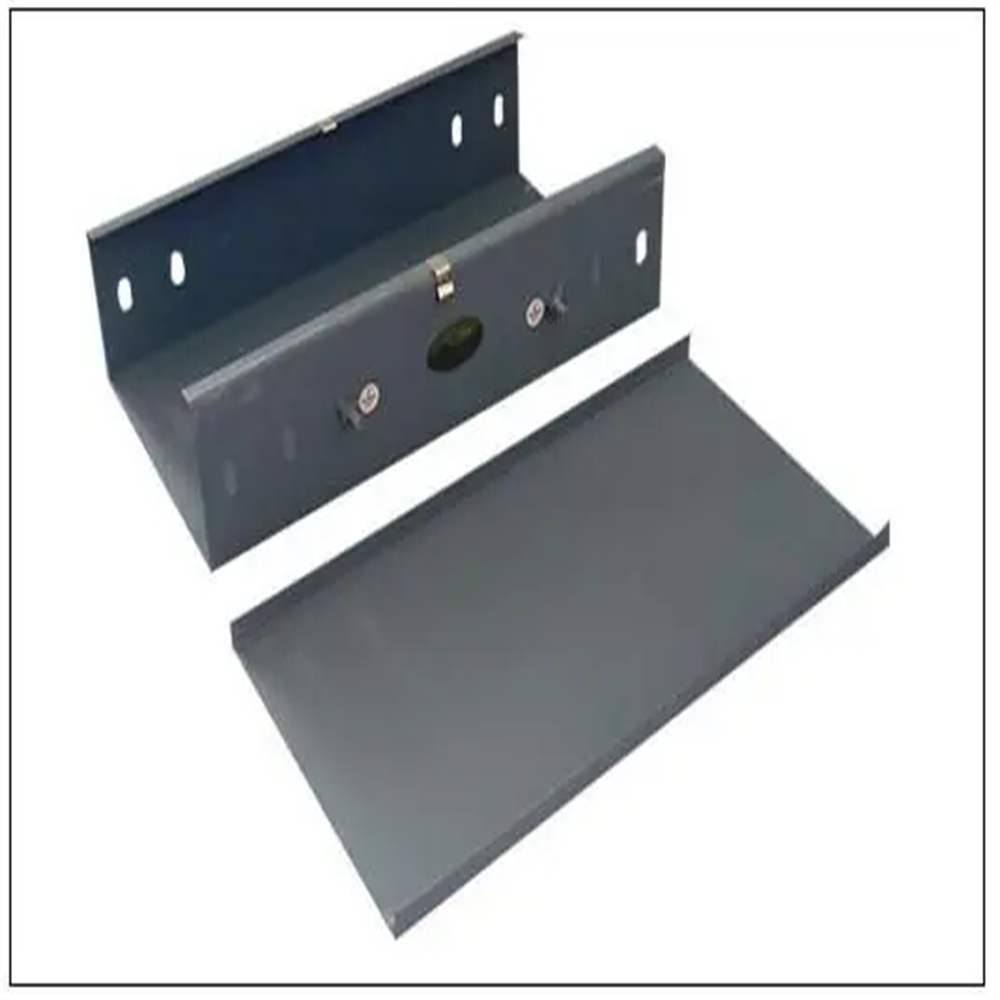
Galvanized cable tray comes in various sizes and shapes, including straight sections, elbows, tees, crosses, and reducers. It is designed to be easy to install and maintain, and can be used in a variety of environments, including indoor and outdoor settings. Galvanized cable tray is commonly used in power plants, chemical plants, oil refineries, and other industrial facilities where there is a need for a reliable and robust cable management system.
One of the benefits of galvanized cable tray is its resistance to corrosion. The zinc coating on the steel provides a protective layer that prevents rust and corrosion from forming on the surface of the tray. This makes galvanized cable tray ideal for use in environments where there is exposure to moisture, chemicals, and other corrosive substances.
Another advantage of galvanized cable tray is its strength. The steel used in galvanized cable tray is strong and durable, which means it can support heavy loads without bending or breaking. This makes it a popular choice for applications where there is a need for a sturdy and reliable cable management system.
Galvanized cable tray is also easy to install and maintain. The tray can be cut to size and shaped to fit around obstacles, making it a flexible solution for cable management. It can also be easily cleaned and maintained, which helps to extend its lifespan and keep it in good condition.

Galvanized Cable Tray,Galvanized Steel Cable Tray,Galvanized Cable Trays,Galvanized Cable Ladder
Rayhot Technology Group Co.,Ltd , https://www.cnrayhot.com